

TANK-620-ULT3 Embedded System
Page 68
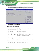
AHCI
D
EFAULT
Configures SATA devices as AHCI device.
RAID
Configures SATA devices as RAID device.
Hot Plug [Disabled]
Use the
Hot Plug
option to enable or disable the hot plug function.
Disabled
D
EFAULT
Disables the hot plug function.
Enabled
Enables the hot plug function.
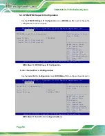
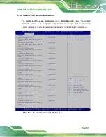
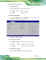
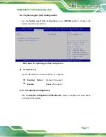
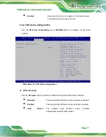
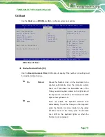
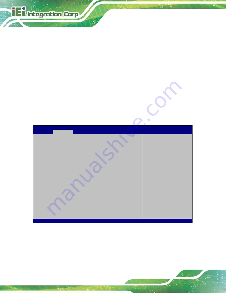
5.3.11 USB Configuration
Use the
USB Configuration
menu (
) to read USB configuration
information and configure the USB settings.
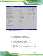
Aptio Setup Utility – Copyright (C) 2018 American Megatrends, Inc.
Advanced
USB Configuration
USB Devices:
1 Keyboard
Legacy USB Support
[Enabled]
Enables Legacy USB
support. AUTO option
disables legacy support
if no USB devices are
connected. DISABLE
option will keep USB
devices available only
for EFI applications.
---------------------
: Select Screen
↑
↓
: Select Item
Enter
Select
+/-: Change Opt.
F1: General Help
F2: Previous Values
F3: Optimized Defaults
F4: Save & Exit
ESC: Exit
Version 2.18.1263. Copyright (C) 2018 American Megatrends, Inc.
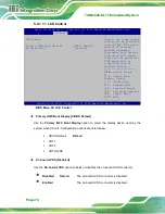
BIOS Menu 19: USB Configuration
USB Devices
The
USB Devices
field lists the USB devices that are enabled on the system
Summary of Contents for TANK-620-ULT3
Page 12: ...TANK 620 ULT3 Embedded System Page 1 Chapter 1 1 Introduction ...
Page 19: ...TANK 620 ULT3 Embedded System Page 8 Chapter 2 2 Unpacking ...
Page 23: ...TANK 620 ULT3 Embedded System Page 12 Chapter 3 3 Installation ...
Page 34: ...TANK 620 ULT3 Embedded System Page 23 4 System Motherboard Chapter 4 ...
Page 47: ...TANK 620 ULT3 Embedded System Page 36 Chapter 5 5 BIOS ...
Page 94: ...TANK 620 ULT3 Embedded System Page 83 Appendix A A Regulatory Compliance ...
Page 99: ...TANK 620 ULT3 Embedded System Page 88 Appendix B B BIOS Options ...
Page 103: ...TANK 620 ULT3 Embedded System Page 92 Appendix C C Terminology ...
Page 107: ...TANK 620 ULT3 Embedded System Page 96 Appendix D D Safety Precautions ...
Page 112: ...TANK 620 ULT3 Embedded System Page 101 Appendix E E Digital I O Interface ...
Page 115: ...TANK 620 ULT3 Embedded System Page 104 Appendix F F Hazardous Materials Disclosure ...


