TANK-700-QM67W-MRAY Em b e d d e d S ys te m
P a g e 26
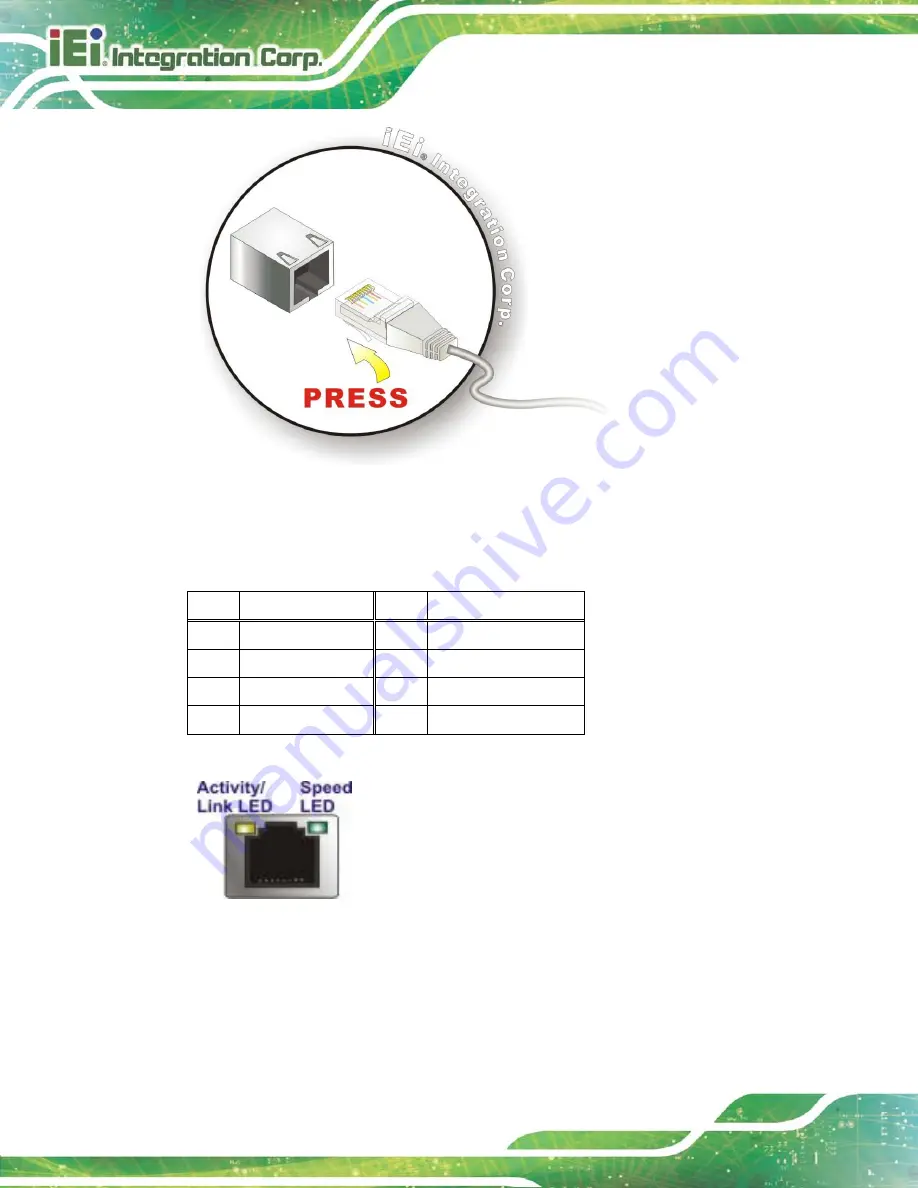
Figure 3-14: LAN Connection
S te p 3:
Insert the LAN cable RJ-45 connector.
Once aligned, gently insert the LAN
cable RJ-45 connector into the on-board RJ-45 connector.
Pin
Description
Pin
Description
1
TRD1P0
5
TRD1P2
2
TRD1N0
6
TRD1N2
3.
TRD1P1
7
TRD1P3
4.
TRD1N1
8
TRD1N3
Table 3-3: LAN Pinouts
Figure 3-15: RJ-45 Ethernet Connector
The RJ-45 Ethernet connector has two status LEDs, one green and one yellow. The green
LED indicates activity on the port and the yellow LED indicates the port is linked. See
Summary of Contents for TANK-700-QM67W-MRAY
Page 10: ...TANK 700 QM67W MRAY Embedded Sys tem Page 1 Chapter 1 1 Introduction ...
Page 18: ...TANK 700 QM67W MRAY Embedded Sys tem Page 9 Chapter 2 2 Unpacking ...
Page 22: ...TANK 700 QM67W MRAY Embedded Sys tem Page 13 Chapter 3 3 Ins tallation ...
Page 52: ...TANK 700 QM67W MRAY Embedded Sys tem Page 43 Chapter 4 4 BIOS ...
Page 88: ...TANK 700 QM67W MRAY Embedded Sys tem Page 79 Appendix A A Safety Precautions ...
Page 93: ...TANK 700 QM67W MRAY Embedded Sys tem Page 84 Appendix B B Hazardous Materials Dis clos ure ...


