TANK-700-QM67W-MRAY Em b e d d e d S ys te m
P a g e 28
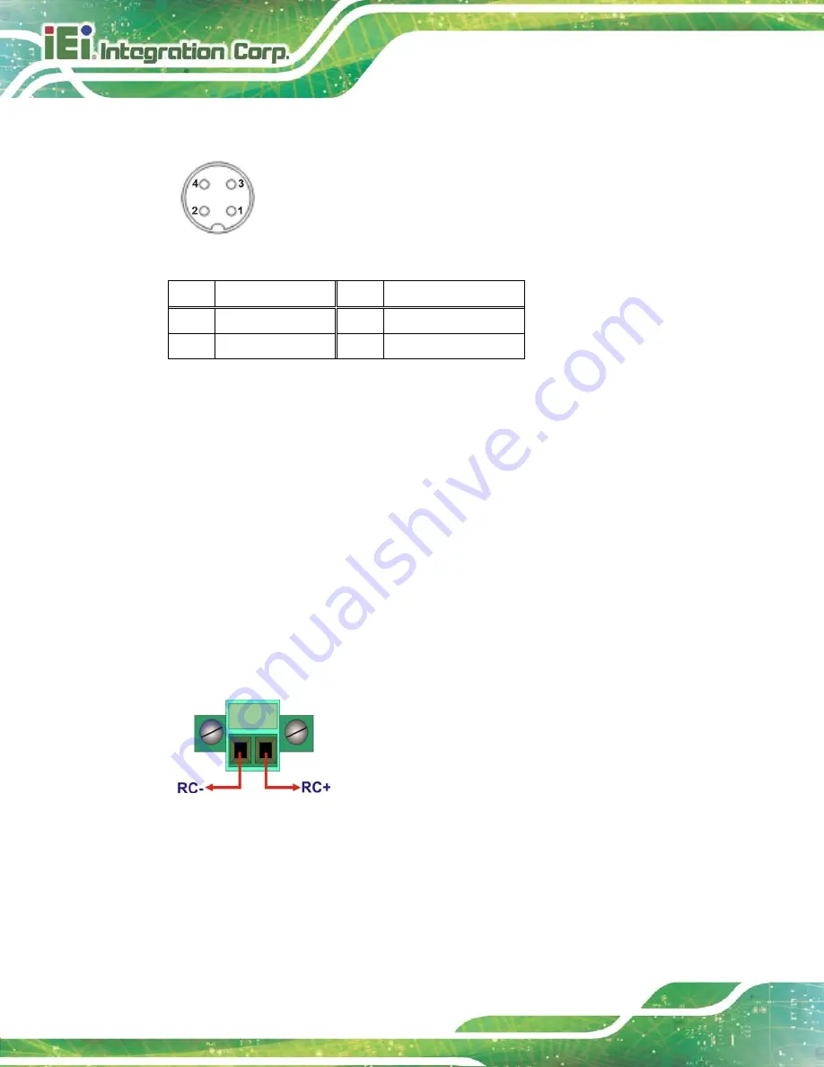
The power connector connects to the 10.5V~36V DC power adapter.
Figure 3-17: Power Input Connector
Pin
Description
Pin
Description
1
+12V
3
+12V
2
GND
4
GND
Table 3-6: Power Input Pinouts
3.7.9
Re m o te Co n tro l Co n n e c to r (Fo r AT P o we r Mo d e On ly)
CN La b e l:
Remoter
CN Typ e :
2-pin terminal block
CN Lo c a tio n :
See
CN P in o u ts :
See
The 2-pin terminal block connects to a remote control device. Users can control the
system power on/off by inputting high or low voltage into the terminal block.
Turn off
the system:
2 V
~
5 V
input
Turn on
the system:
less than 0.4 V
input
Figure 3-18: Remote Control Terminal Block Pinout Location
Summary of Contents for TANK-700-QM67W-MRAY
Page 10: ...TANK 700 QM67W MRAY Embedded Sys tem Page 1 Chapter 1 1 Introduction ...
Page 18: ...TANK 700 QM67W MRAY Embedded Sys tem Page 9 Chapter 2 2 Unpacking ...
Page 22: ...TANK 700 QM67W MRAY Embedded Sys tem Page 13 Chapter 3 3 Ins tallation ...
Page 52: ...TANK 700 QM67W MRAY Embedded Sys tem Page 43 Chapter 4 4 BIOS ...
Page 88: ...TANK 700 QM67W MRAY Embedded Sys tem Page 79 Appendix A A Safety Precautions ...
Page 93: ...TANK 700 QM67W MRAY Embedded Sys tem Page 84 Appendix B B Hazardous Materials Dis clos ure ...


