TANK-870AI Embedded System
Page 25
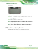
Left Side Panel
Figure 3-7: Mounting Bracket Retention Screws
Step 3:
Secure the brackets to the system by inserting two retention screws into each
bracket (
).
Step 4:
Drill holes in the intended installation surface.
Step 5:
Align the mounting holes in the sides of the mounting brackets with the predrilled
holes in the mounting surface.
Step 6:
Insert four retention screws, two in each bracket, to secure the system to the
wall.
3.6 External Peripheral Interface Connectors
Detailed descriptions of the connectors can be found in the subsections below.
Summary of Contents for TANK-870AI SERIES
Page 14: ...TANK 870AI Embedded System Page XIV BIOS Menu 31 PCH Azalia Configuration Menu 99 ...
Page 15: ...TANK 870AI Embedded System Page 1 Chapter 1 1 Introduction ...
Page 27: ...TANK 870AI Embedded System Page 13 Chapter 2 2 Unpacking ...
Page 33: ...TANK 870AI Embedded System Page 19 Chapter 3 3 Installation ...
Page 57: ...TANK 870AI Embedded System Page 43 4 System Motherboard Chapter 4 ...
Page 69: ...TANK 870AI Embedded System Page 55 Chapter 5 5 BIOS ...
Page 114: ...TANK 870AI Embedded System Page 100 Appendix A A Regulatory Compliance ...
Page 119: ...TANK 870AI Embedded System Page 105 Appendix B B BIOS Options ...
Page 123: ...TANK 870AI Embedded System Page 109 Appendix C C Terminology ...
Page 127: ...TANK 870AI Embedded System Page 113 Appendix D D Safety Precautions ...
Page 132: ...TANK 870AI Embedded System Page 118 Appendix E E Digital I O Interface ...
Page 135: ...TANK 870AI Embedded System Page 121 Appendix F F Hazardous Materials Disclosure ...

