background image

TANK-XM810


Page 85 

5.4.1


System Agent (SA) Configuration 

Use  the 

System  Agent  (SA)  Configuration 

menu  (

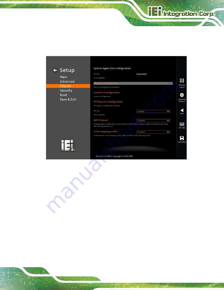
BIOS Menu 24

)  to  configure  the 

System Agent (SA) parameters. 


BIOS Menu 24: System Agent (SA) Configuration 


VT-d [Enabled] 

Use the

 VT-d

 option to enable or disable the VT-d capability.   


Disabled 


Disable the VT-d capability 


Enabled 

D

EFAULT


Enable the VT-d capability 


WRC Feature [Enabled] 

Use the


WRC Feature option to enable or disable the capability of writing cache.   


Disabled 


Disable the WRC Feature capability 


Enabled 

D

EFAULT


Enable the WRC Feature capability 

Summary of Contents for TANK-XM810 Series

Page 1: ... Manual Embedded System with 10th 11th Generation Intel Core Processor Two DDR4 Slot Digital I O HDMI DP Two Gigabit Ethernet RS 232 422 485 RoHS Compliant TANK XM810 Series MODEL Rev 1 01 September 23 2022 ...

Page 2: ...I TANK XM810 Revisions Date Version Changes September 22 2022 1 01 Added BIOS Section Added System Jumper Configuration in Section 4 4 Added RAID Configuration in Section 3 8 May 30 2022 1 00 Initial release ...

Page 3: ...sing out of the use or inability to use the product or documentation even if advised of the possibility of such damages This document contains proprietary information protected by copyright All rights are reserved No part of this manual may be reproduced by any mechanical electronic or other means in any form without prior written permission of the manufacturer TRADEMARKS All registered trademarks...

Page 4: ...utionary messages should be heeded to help reduce the chance of losing data or damaging the product NOTE These messages inform the reader of essential but non critical information These messages should be read carefully as any directions or instructions contained therein can help avoid making mistakes HOT SURFACE This symbol indicates a hot surface that should not be touched without taking care ...

Page 5: ...ALLATION PRECAUTIONS 17 3 2 CPU RAM STORAGE INSTALLATION 18 3 3 MOUNTING THE SYSTEM WITH MOUNTING BRACKETS 22 3 4 EXTERNAL PERIPHERAL INTERFACE CONNECTORS 23 3 4 1 AT ATX Power Mode Selection 24 3 4 2 SYS_FAN Connector 24 3 4 3 Digital Input Output Connector 25 3 4 4 HDMI DP Connector 25 3 4 5 LAN Connectors 26 3 4 6 Power Input 4 pin Terminal Block 27 3 4 7 Power Input 4 pin DIN Connector 27 3 4 ...

Page 6: ...rd Connector DEBUG_SPI1 43 4 2 8 LAN LED Connector LED_LAN1 LED_LAN2 LED_LAN3 43 4 2 9 Battery Connector BAT1 43 4 3 EXTERNAL INTERFACE PANEL CONNECTORS 44 4 3 1 HDMI Connector HDMI1 45 4 3 2 DP Connector DP1 45 4 3 3 USB 3 2 Gen 2 Connectors CON1 46 4 3 4 USB 2 0 Connectors USB2_1 46 4 3 5 RS 232 422 485 Serial Port Connectors CN1 COM5 6 47 4 3 6 RS 232 Connectors COM1 COM4 48 4 3 7 LAN Connector...

Page 7: ...69 5 3 4 3 Serial Port 3 Configuration 70 5 3 4 4 Serial Port 4 Configuration 71 5 3 4 5 Serial Port 5 Configuration 72 5 3 4 6 Serial Port 6 Configuration 73 5 3 5 ENE KB9068 Monitor 74 5 3 5 1 Smart Fan Mode Configuration 76 5 3 6 Serial Port Console Redirection 78 5 3 6 1 Console Redirection Settings 79 5 3 7 Intel TXT Information 82 5 3 8 NVMe Configuration 83 5 4 CHIPSET 84 5 4 1 System Agent...

Page 8: ...NCE 102 B SAFETY PRECAUTIONS 107 B 1 SAFETY PRECAUTIONS 108 B 1 1 General Safety Precautions 108 B 1 2 Anti static Precautions 109 B 1 3 Product Disposal 110 B 2 MAINTENANCE AND CLEANING PRECAUTIONS 110 B 2 1 Maintenance and Cleaning 111 B 2 2 Cleaning Tools 111 C BIOS OPTIONS 112 D ERROR BEEP CODE 116 D 1 DXE BEEP CODES 117 E HAZARDOUS MATERIALS DISCLOSURE 118 E 1 ROHS II DIRECTIVE 2015 863 EU 11...

Page 9: ...Figure 3 10 Mounting Bracket Retention Screws 22 Figure 3 11 AT ATX Power Mode Switch 24 Figure 3 12 SYS_FAN Connector 24 Figure 3 13 DIO Connector 25 Figure 3 14 HDMI DP Connection 25 Figure 3 15 LAN Connection 26 Figure 3 16 RJ 45 Ethernet Connector 26 Figure 3 17 4 pin Terminal Block 27 Figure 3 18 Power Input Connector 27 Figure 3 19 DB 9 RS 232 422 485 Serial Port Connector 28 Figure 3 20 Ser...

Page 10: ...ure 3 30 Flash Descriptor Security Override Jumper Location 37 Figure 4 1 System Motherboard Front 39 Figure 4 2 System Motherboard Rear 40 Figure 4 3 HDMI Connector 45 Figure 4 4 DP Connector 46 Figure 4 5 USB 2 0 Connector 47 Figure 4 6 RS 232 422 485 Serial Port Connectors 47 Figure 4 7 Ethernet Connector 48 Figure 4 8 AT ATX Power Mode Switch 50 Figure 4 9 Clear CMOS Button 50 ...

Page 11: ...nouts 42 Table 4 4 BIOS Programming Connector Pinouts 42 Table 4 5 EC Programmer Connector Pinouts 42 Table 4 6 Power Button Connector Pinouts 43 Table 4 7 EC UART Debug Connector Pinouts 43 Table 4 8 EC Debug Card Connector Pinouts 43 Table 4 9 LAN LED Connector Pinouts 43 Table 4 10 Battery Connector Pinouts 43 Table 4 11 Rear Panel Connectors 44 Table 4 12 HDMI Connector Pinouts 45 Table 4 13 D...

Page 12: ...put Connector Pinouts 49 Table 4 24 External Peripheral Connectors 49 Table 4 25 AT ATX Power Mode Switch Pinouts 50 Table 4 26 Clear CMOS Button Pinouts 50 Table 5 1 BIOS Navigation Keys 53 Table 5 2 BIOS On screen Navigation Keys 54 Table 5 3 BIOS Options and Configured USB Ports 92 ...

Page 13: ...TANK XM810 Page 1 Chapter 1 1 Introduction ...

Page 14: ...vironments It is powered by 10th 11th generation Intel Core processor with Q470 chipset and has two 260 pin DDR4 SDRAM SO DIMM slots supporting up to 64GB memory 8GB preinstalled The TANK XM810 Series includes one digital I O port one HDMI one DP two GbE LAN six USB 3 2 Gen 2 two USB 2 0 two RS 232 422 485 and four RS 232 connectors ...

Page 15: ...4 2GHz 6 core TDP 65W TANK XM810 i7AC R10 Intel Core i7 10700TE 2 0GHz up to 4 4GHz 8 core TDP 35W TANK XM810 i7BC R10 Intel Core i7 10700E 2 9GHz up to 4 5GHz 8 core TDP 65W Table 1 1 TANK XM810 Series Model Variations 1 3 Features The TANK XM810 Series features are listed below 10th 11th Gen Intel Core processor platform with Intel Q470 chipset and DDR4 memory Dual independent displays with high...

Page 16: ...tel Core i7 10700TE 2 0GHz up to 4 4GHz 8 core TDP 35W Intel Core i5 10500TE 2 3GHz up to 3 7GHz 6 core TDP 35W Intel Core i3 10320 3 8GHz up to 4 6GHz 4 core TDP 65W Chipset Intel Q470 Q470E System Memory 2 x SO DIMM DDR4 2933MHz up to 64GB Storage Hard Drive 1 x 2 5 HDD SSD SATA 6Gb s bay I O Interfaces USB 3 2 Gen 2 10Gb s 6 USB 2 0 2 RS 232 422 485 2 x RS 232 422 485 2 x RS232 Ethernet Two RJ ...

Page 17: ...ting Temperature 20 C 60 C with air flow CPU TDP 35W SSD 20 C 50 C with air flow CPU TDP 65W SSD 10 95 non condensing Storage Temperature 40 C 85 C 10 95 non condensing Operating Shock Half sine wave shock 5G 11ms 100 shocks per axis SSD Operating Vibration MIL STD 810G 514 6C 1 with SSD Weight Net Gross 3 33 kg 3 7 kg Safety EMC CE FCC Watchdog Timer Programmable 1 255 sec min OS Supported OS Mic...

Page 18: ...Page 6 TANK XM810 1 5 Front Panel The front panel of the TANK XM810 Series has the following features See Figure 1 2 Figure 1 2 Front Panel ...

Page 19: ...TANK XM810 Page 7 1 6 Rear Panel The rear panel of the TANK XM810 Series is shown below See Figure 1 3 Figure 1 3 Rear Panel ...

Page 20: ...Page 8 TANK XM810 1 7 Physical Dimensions The physical dimensions of the TANK XM810 are shown below See Figure 1 4 Figure 1 4 Physical Dimensions ...

Page 21: ...TANK XM810 Page 9 Chapter 2 2 Unpacking ...

Page 22: ... Wearing a simple anti static wristband can help to prevent ESD from damaging the board Self grounding Before handling the board touch any grounded conducting material During the time the board is handled frequently touch any conducting materials that are connected to the ground Use an anti static pad When configuring the TANK XM810 Series place it on an antic static pad This reduces the possibili...

Page 23: ...ion Contact the IEI reseller or vendor you purchased the TANK XM810 Series from or contact an IEI sales representative directly To contact an IEI sales representative please send an email to sales ieiworld com The TANK XM810 Series is shipped with the following components Quantity Item and Part Number Image Standard 1 TANK XM810 Series 2 Mounting brackets ...

Page 24: ... Number Image Standard 1 2 pin Terminal block 1 4 pin Terminal block 1 Chassis screws Table 2 1 Standatd Packing List The following table lists the optional items that can be purchased separately Optional Wi Fi module P N EMB WIFI KIT02I3 R10 ...

Page 25: ...40 010180 200 RSSS Power cord P N 32000 000002 RS 8 Port POE LAN Card P N GPOE XM81 8P R10 M 2 PCIe Mini expansion card P N TXIOB XM81 A R10 2 Slot Backplane PCIe x16 PCIe x4 P N TXCBP XM81 2A R10 2 Slot Backplane Two PCIe x8 P N TXCBP XM81 2B R10 ss ...

Page 26: ...ot Backplane Two PCIe x8 Two PCIe x4 P N TXCBP XM81 4B R10 4 Slot Backplane PCIe x16 PCIe x4 Two PCI P N TXCBP XM81 4C R10 4 Slot Backplane PCIe x16 Two PCIe x4 PCIe x1 P N TXCBP XM81 G1 PW R10 4 Slot Backplane Two PCIe x8 Two PCIe x4 P N TXCBP XM81 G2 PW R10 Expansion Power Board P N IDD X1228150 R10 ...

Page 27: ...aphics card support P N TXC XM81 G1 R10 6 Slot Chassis Two Full length graphics card support P N TXC XM81 G2 R10 Expansion Fan Module P N SF TANK XM81 R10 Table 2 2 Optional Packing List NOTE 1 EMB WIFI KIT02I3 R10 needs to be used with TXIOB XM81 A R10 2 TXCBP XM81 series backplane needs to be used with TXC XM81 series chassis ...

Page 28: ...Page 16 TANK XM810 Chapter 3 3 Installation ...

Page 29: ...ear panel of the TANK XM810 Series is opened while the power cord is still connected to an electrical outlet Qualified Personnel The TANK XM810 Series must be installed and operated only by trained and qualified personnel Maintenance upgrades or repairs may only be carried out by qualified personnel who are familiar with the associated dangers Air Circulation Make sure there is sufficient air circ...

Page 30: ...the steps below Step 1 Remove the 6 screws on the side and then remove the top cover See Figure 3 1 Figure 3 1 Remove the Cover Step 2 Remove the 11 spring screws on the motherboard and then take out the motherboard including the motherboard holder See Figure 3 2 Figure 3 2 Take out the motherboard ...

Page 31: ...remove the CPU protection cover install the CPU at the notch and fasten the lever down in the buckle See Figure 3 3 Figure 3 3 CPU Installation Step 4 Place a thermal pad on the heat conductive block of CPU See Figure 3 4 Figure 3 4 CPU Thermal Pad Installation ...

Page 32: ...t sink and lock the motherboard with 11 spring screws See Figure 3 5 Figure 3 5 Motherboard Installation Step 6 Insert the memory into the motherboard memory slot and press it into place See Figure 3 6 Figure 3 6 RAM Installation Step 7 Remove the M 2 2280 reserved screws install the M 2 2280 NVME card and re lock the fixing screws See Figure 3 7 ...

Page 33: ...ion Step 8 Place the hard drive into the hard drive bracket and secure the HDD bracket and the hard drive with four screws See Figure 3 8 Figure 3 8 HDD Installation Step 9 Install the back cover And lock the 6 screws on the side See Figure 3 9 ...

Page 34: ...ng the two mounting brackets please follow the steps below Step 1 Turn the embedded system over Step 2 Align the retention screw holes in each bracket with the corresponding retention screw holes on the bottom surface Step 3 Secure the brackets to the system by inserting retention screws into each bracket See Figure 3 10 Figure 3 10 Mounting Bracket Retention Screws ...

Page 35: ...rface Step 6 Insert four retention screws three in each bracket to secure the system to the wall 3 4 External Peripheral Interface Connectors The TANK XM810 Series has the following connectors Detailed descriptions of the connectors can be found in the subsections below AT ATX power mode switch Digital I O Ethernet Power button Power DC jack Power terminal block HDMI DP RS 232 422 485 USB ...

Page 36: ...The setting can be made through the AT ATX power mode switch on the external peripheral interface panel as shown below See Figure 3 11 Figure 3 11 AT ATX Power Mode Switch 3 4 2 SYS_FAN Connector The SYS_FAN connector can be connected to an external expansion fan See Figure 3 12 Figure 3 12 SYS_FAN Connector ...

Page 37: ...See Table 3 1 Figure 3 13 PIN NO DESCRIPTION PIN NO DESCRIPTION 1 GND 2 DIN0 3 DIN1 4 DIN2 5 DIN3 6 DIN4 7 DIN5 8 GND 9 DOUT0 10 DOUT1 11 DOUT2 12 DOUT3 13 DOUT4 14 DOUT5 15 5VS Table 3 1 Digital I O Connector Pinouts Figure 3 13 DIO Connector 3 4 4 HDMI DP Connector To connect the HDMI DP devices please plug in HDMI DP connector in the right direction as shown below See Figure 3 14 Figure 3 14 HD...

Page 38: ...with one of the RJ 45 connectors on the TANK XM810 Series See Figure 3 15 Figure 3 15 LAN Connection Step 3 Insert the LAN cable RJ 45 connector Once aligned gently insert the LAN cable RJ 45 connector into the on board RJ 45 connector See Figure 3 16 Figure 3 16 RJ 45 Ethernet Connector The RJ 45 Ethernet connector has two status LEDs one green and one yellow The green LED indicates activity on t...

Page 39: ...nnector LEDs 3 4 6 Power Input 4 pin Terminal Block The power connector connects the leads of a 12 V 28 V DC power supply into the terminal block Make sure that the power and ground wires are attached to the correct sockets of the connector See Figure 3 17 Figure 3 17 4 pin Terminal Block 3 4 7 Power Input 4 pin DIN Connector The power connector connects to the 12 V 28 V DC power adapter See Figur...

Page 40: ...5 serial ports The pinouts for the serial ports are listed in the Table 3 3 PIN NO RS232 RS422 RS485 1 DCD TX TX 2 RXD TX TX 3 TXD RX 4 DTR RX 5 GND 6 DSR 7 RTS 8 CTS 9 RI Table 3 3 RS 232 COM1 COM4 RS 422 485 COM5 6 Connector Pinouts Figure 3 19 DB 9 RS 232 422 485 Serial Port Connector Figure 3 20 Serial Device Connection ...

Page 41: ...System WARNING Make sure a power supply with the correct input voltage is being fed into the system Incorrect voltages applied to the system may cause damage to the internal electronic components and may also cause injury to the user Power on the system press the power button for 3 seconds Power off the system press the power button for 6 seconds The power of this system can be less than 250w 20A ...

Page 42: ...r adapter The supported power input voltages are Power 1 Terminal block 12 V 28 V Power 2 DC jack 12 V 28 V Power LED Power 1 DC Jack 12 28V Power 2 Terminal Block 12 28V Figure 3 23 Power Connectors LED Indicator Description Power LED1 Breathing Orange Standby mode Power LED2 Solid blue Power on mode Table 3 4 Power LED Indicators Description NOTE The power LED turns off when the power cable is u...

Page 43: ...ind all the relevant software utilities and documentation Figure 3 24 IEI Resource Download Center 3 7 1 Driver Download To download drivers from IEI Resource Download Center follow the steps below Step 1 Go to Uhttps download ieiworld comU Type TANK XM810 Series and press Enter Step 2 All product related software utilities and documentation will be listed You can choose Driver to filter the resul...

Page 44: ...ollowing window You can download the entire ISO file or click the small arrow to find an individual driver and click the file name to download NOTE To install software from the downloaded ISO image file in Windows 10 or later double click the ISO file to mount it as a virtual drive to view its content ...

Page 45: ... identified by attaching stickers to the drive bays If a drive member of a RAID array should fail the failed drive can then be correctly identified CAUTION Do not accidentally disconnect the drive cables Carefully route the cables within the chassis to avoid system down time Step 1 Connect the drives to the system Connect two or more drives to the system Make sure the drives have the same capacity...

Page 46: ...Figure 3 25 RAID Configuration BIOS Setting 1 Step 3 Save and Exit BIOS After the option Intel RST With Intel Optane System Acceleration is enabled save and exit the BIOS Step 4 Reboot the system Reboot the system after saving and exiting the BIOS Step 5 Configure the RAID settings in BIOS Go to Advanced Intel Rapid Storage Technology Use the option to configure the RAID array See Figure 3 26 Figu...

Page 47: ... the Main Menu and press Enter Figure 3 27 Create RAID Volume from the Main Menu Step 7 Press the up down arrows on the keyboard to choose the RAID Level and select the disks for the RAID configuration See Figure 3 28 Figure 3 28 Choose the RAID Level and select the Disks ...

Page 48: ... See Figure 3 29 Figure 3 29 Confirm to create the RAID Volume 3 9 Maintenance To configure the jumper settings please follow the steps below Step 1 Remove the top cover See Figure 3 2 Step 2 Locate the jumper on the embedded motherboard Step 3 Make the jumper settings in accordance with the settings described and defined in the following sections ...

Page 49: ...scriptor Security Override Jumper Settings Figure 3 30 Flash Descriptor Security Override Jumper Location To update the ME firmware please follow the steps below Step 1 Before turning on the system power short the Flash Descriptor Security Override jumper Step 2 Update the BIOS and ME firmware and then turn off the system power Step 3 Remove the metal clip on the Flash Descriptor Security Override...

Page 50: ...Page 38 TANK XM810 4 System Motherboard Chapter 4 ...

Page 51: ... 4 1 Overview This chapter details all the jumpers and connectors of the system motherboard 4 1 1 Layout The figures below show all the connectors and jumpers of the system motherboard Figure 4 1 System Motherboard Front ...

Page 52: ...Page 40 TANK XM810 Figure 4 2 System Motherboard Rear ...

Page 53: ... EC_JSP1 EC debug card connector 6 pin box header DEBUG _SPI1 EC UART connector 4 pin box header EC_UART1 Flash Override jumper 3 pin header J_FLASH1 I2C BUS connector 4 pin box header I2C1 SMBUS connector 4 pin box header SMB1 M 2 slot PCIe x2 interface M 2 M key slot M2_M1 M 2 slot PCIe x2 interface M 2 M key slot M2_M2 HDD backplane connector PCIE x1 slot PCIEX1_1 DDR4 memory slot DDR4 memory s...

Page 54: ...LK_MAIN 4 V5S 4 2 3 BIOS Programming Connector JSPI1 PIN NO DESCRIPTION PIN NO DESCRIPTION 1 V3 3M_SPI_CON 2 SPI_CS 0_SW 3 SPI_SO_SW 4 SPI_CLK_SW 5 SPI_SI_SW 6 GND Table 4 4 BIOS Programming Connector Pinouts 4 2 4 EC Programmer Connector EC_SPI1 PIN NO DESCRIPTION PIN NO DESCRIPTION 1 EC_SPI_CS _R 2 V3 3A_EC 3 EC_SPI_MISO_R 4 NC 5 EC_DET_FLASH 6 EC_SPI_CLK_R 7 GND 8 EC_SPI_MOSI_R Table 4 5 EC Pro...

Page 55: ... 4 GND Table 4 7 EC UART Debug Connector Pinouts 4 2 7 EC Debug Card Connector DEBUG_SPI1 PIN NO DESCRIPTION PIN NO DESCRIPTION 1 EC_SPI_CS _R 2 V3 3A_EC 3 EC_SPI_MISO_R 4 NC 5 EC_DET_FLASH 6 EC_SPI_CLK_R Table 4 8 EC Debug Card Connector Pinouts 4 2 8 LAN LED Connector LED_LAN1 LED_LAN2 LED_LAN3 PIN NO DESCRIPTION 1 VCC3V 2 ACT Table 4 9 LAN LED Connector Pinouts 4 2 9 Battery Connector BAT1 PIN ...

Page 56: ...lock PWR2 DP and HDMI Connector DisplayPorts HDMI HDMI_DP1 USB 2 0 USB 2 0 USB 2_1 USB 3 2 Gen 2 USB 3 2 Gen 2 CN1 Ethernet and USB 3 2 Gen 2 combo connectors RJ 45 USB 3 2 Gen 2 Type A LAN1_USB1 LAN2_USB2 RS 232 422 485 connector DB 9 COM5 COM6 RESET Switch 4 pin Switch RST1 HDD System LED HDD System LED HDD_PWR_L1 Power button connector 4 pin Switch PWR_BTN1 RS 232 connector DB 9 COM1 COM2 COM3 ...

Page 57: ...MI_HPD 8 GND 20 HDMI_GND 9 HDMI_DATA0 21 HDMI_GND 10 HDMI_CLK 22 HDMI_GND 11 GND 23 HDMI_GND 12 HDMI_CLK Table 4 12 HDMI Connector Pinouts Figure 4 3 HDMI Connector 4 3 2 DP Connector DP1 PIN NO DESCRIPTION PIN NO DESCRIPTION 1 LANE0P 11 GND 2 LANE0N 12 LANE3N 3 GND 13 DP_EN_DT 4 LANE1P 14 EN 5 LANE1N 15 AUXP 6 GND 16 GND 7 LANE2P 17 AUXN 8 GND 18 HPD 9 LANE2N 19 GND 10 LANE3P 20 3 3V Table 4 13 D...

Page 58: ...B_DATA 12 USB_ DATA 4 GND 13 GND 5 USB3_RX 14 USB3_RX 6 USB3_RX 15 USB3_ RX 7 GND 16 GND 8 USB3_TX 17 USB3_TX 9 USB3_TX 18 USB3_TX Table 4 14 USB 3 2 Gen 2 Connector Pinouts 4 3 4 USB 2 0 Connectors USB2_1 The system provides two USB 2 0 connectors for USB device connection PIN NO DESCRIPTION PIN NO DESCRIPTION 1 USB_VCC 5 USB_VCC 2 DATA 6 DATA 3 DATA 7 DATA 4 GND 8 GND Table 4 15 USB 2 0 Connecto...

Page 59: ...al Port Connectors CN1 COM5 6 Mode RS 232 RS 422 RS 485 PIN NO DESCRIPTION DESCRIPTION DESCRIPTION 1 DCD TX TX 2 RXD TX TX 3 TXD RX 4 DTR RX 5 GND 6 DSR 7 RTS 8 CTS 9 RI Table 4 16 RS 232 422 485 Serial Port Connector Pinouts Figure 4 6 RS 232 422 485 Serial Port Connectors ...

Page 60: ...IN NO DESCRIPTION 1 MDIA3 5 MDIA1 2 MDIA3 6 MDIA2 3 MDIA2 7 MDIA0 4 MDIA1 8 MDIA0 Table 4 18 LAN Connector Pinouts Figure 4 7 Ethernet Connector LED Description LED Description A on linked blinking data is being sent received B off 10 Mb s green 100 Mb s orange 1000 Mb s Table 4 19 Connector LEDs 4 3 8 Remote Power BTN Connector JP1 PIN NO DESCRIPTION PIN NO DESCRIPTION 1 PWRBTN_SW 2 GND Table 4 2...

Page 61: ...DC_IN1 2 GND 3 DC_IN1 4 GND 5 GND Table 4 22 Power Input Connector Pinouts 4 3 11 Power Input Connector Terminal Block PWR2 PIN NO DESCRIPTION PIN NO DESCRIPTION 1 DC_IN2 2 DC_IN2 3 GND 4 GND Table 4 23 Power Input Connector Pinouts 4 4 System Jumper Settings The table below shows a list of the Jumper Settings of the system Label Function J_ATX_AT1 AT ATX Power Mode Setting J_CMOS1 Clear CMOS Setu...

Page 62: ...ure 4 8 AT ATX Power Mode Switch 4 4 2 Clear CMOS Setup J_CMOS1 To clear the CMOS Setup for example if you have forgotten the password you should clear the CMOS and then reset the password you should take off the battery BT1 and press the button for about 3 seconds This will set back to normal operation mode PIN NO DESCRIPTION NC Keep CMOS Setup Normal Operation Press button Clear CMOS Setup Table...

Page 63: ...TANK XM810 Page 51 Chapter 5 5 BIOS ...

Page 64: ... 5 1 1 Starting Setup The UEFI BIOS is activated when the computer is turned on The setup program can be activated in one of two ways 1 Using keyboard Press the DEL or F2 as soon as the system is turned on 2 Using touchscreen Press the Setup button on the upper right corner of the BIOS Starting Menu If the message disappears before the DEL or F2 key is pressed restart the computer and try again th...

Page 65: ... on the right hand side Increase the numeric value or make changes Decrease the numeric value or make changes Page Up Move to the previous page Page Dn Move to the next page Esc Main Menu Quit and not save changes into CMOS Status Page Setup Menu and Option Page Setup Menu Exit current page and return to Main Menu F1 General help only for Status Page Setup Menu and Option Page Setup Menu F2 Load p...

Page 66: ...On screen Button Function Previous Values Load the last value you set Optimized Defaults Load the factory default values in order to achieve the best performance Back Return to the previous menu Soft kbd Display the on screen keyboard Save Exit Save the changes made to the BIOS options and reset the system Table 5 2 BIOS On screen Navigation Keys ...

Page 67: ...efaults Use the clear CMOS button described in Chapter 4 5 1 5 BIOS Menu Bar The menu bar on top of the BIOS screen has the following main items Main Changes the basic system configuration Advanced Changes the advanced system settings Chipset Changes the chipset settings Security Sets User and Supervisor Passwords Boot Changes the system boot configuration Save Exit Selects exit options and loads ...

Page 68: ...Page 56 TANK XM810 5 2 Main The Main BIOS menu appears when the BIOS Setup program is entered The Main menu gives an overview of the basic system information BIOS Menu 3 Main 1 2 ...

Page 69: ...TANK XM810 Page 57 BIOS Menu 4 Main 2 2 ...

Page 70: ...r details Type Displays the processor type Speed Displays the processor speed ID Displays the processor ID Stepping Displays the processor stepping Package Displays the processor package Number of Processors Displays number of CPU cores Microcode Revision CPU microcode revision GT Info Processor GT Info Only valid if SNB stepping is D0 or above IGFX GOP Version Displays the IGFX GOP version PCIe G...

Page 71: ... Freq Displays the frequency of writing and eraseing clock frequency ME FW Version Displays the ME firmware version ME Firmware SKU Displays the ME firmware SKU PMC FW Version Displays the PMC firmware version The System Overview field also has two user configurable fields System Date xx xx xx Use the System Date option to set the system date Manually enter the day month and year System Time xx xx...

Page 72: ...Menu 5 to configure the CPU and peripheral devices through the following sub menus WARNING Setting the wrong values in the sections below may cause the system to malfunction Make sure that the settings made are compatible with the hardware BIOS Menu 5 Advanced ...

Page 73: ...M810 Page 61 5 3 1 CPU Configuration Use the CPU Configuration menu BIOS Menu 6 BIOS Menu 7 to view detailed CPU specifications or enable the Intel Virtualization Technology BIOS Menu 6 CPU Configuration 1 2 ...

Page 74: ...tualization Technology option to enable or disable virtualization on the system When combined with third party software Intel Virtualization technology allows several OSs to run on the same system at the same time Disabled Disables Intel Virtualization Technology Enabled DEFAULT Enables Intel Virtualization Technology ...

Page 75: ...per Threading Technology Enabled DEFAULT Enables Hyper Threading Technology Intel R Trusted Execution Technology Disabled Use the Intel Trusted Execution Technology Intel TXT option to enable or disable utilization of additional hardware capabilities provided by Intel R Trusted Execution Technology Disabled DEFAULT Disables Intel TXT Technology Enabled Enables Intel TXT Technology Intel R SpeedSte...

Page 76: ...ctivation Offset Technology Power Limit 1 Use the or key to change the Power Limit 1 value BIOS will program the default values for Limit 1 and Power Limit 1 Time Window For 12 50W enter 12500 Power Limit 1 Time Window 0 Use the Power Limit 1 Time Window option to select the PL1 time duration The value may vary from 0 to 128 For 0 is the default value Power Limit 2 Use the or key to change the Pow...

Page 77: ... Menu 8 PCH FW Configuration Security Device Support Enabled Use the Security Device Support option to configure support for the TPM Disable TPM support is disabled Enable DEFAULT TPM support is enabled Pending Operation None Use the Pending Operation option to schedule an operation for the security device None DEFAULT TPM information is previous TPM Clear TPM information is cleared ...

Page 78: ...Wake System with Fixed Time Disabled Use the Wake System with Fixed Time option to specify the time the system should be roused from a suspended state Disabled DEFAULT The real time clock RTC cannot generate a wake event Enabled If selected the following appears with values that can be selected Wake up every day Wake up date Wake up hour ...

Page 79: ... alarm the computer turns itself on from a suspend state when the alarm goes off 5 3 4 F81866 Super IO Configuration Use the F81866 Super IO Configuration menu BIOS Menu 10 to set or change the configurations for the serial ports BIOS Menu 10 F81866 Super IO Configuration ...

Page 80: ... 1 Configuration Menu Serial Port Enabled Use the Serial Port option to enable or disable the serial port Disabled Disable the serial port Enabled DEFAULT Enable the serial port Device Settings The Device Settings option shows the serial port IO port address and interrupt address IO 3F8h IRQ 4 Serial Port I O port address is 3F8h and the interrupt address is IRQ4 ...

Page 81: ... 2 Configuration Menu Serial Port Enabled Use the Serial Port option to enable or disable the serial port Disabled Disable the serial port Enabled DEFAULT Enable the serial port Device Settings The Device Settings option shows the serial port IO port address and interrupt address IO 2F8h IRQ 3 Serial Port I O port address is 2F8h and the interrupt address is IRQ3 ...

Page 82: ...3 Configuration Menu Serial Port Enabled Use the Serial Port option to enable or disable the serial port Disabled Disable the serial port Enabled DEFAULT Enable the serial port Device Settings The Device Settings option shows the serial port IO port address and interrupt address IO 2E0h IRQ 10 Serial Port I O port address is 2E0h and the interrupt address is IRQ10 ...

Page 83: ...4 Configuration Menu Serial Port Enabled Use the Serial Port option to enable or disable the serial port Disabled Disable the serial port Enabled DEFAULT Enable the serial port Device Settings The Device Settings option shows the serial port IO port address and interrupt address IO 2E8h IRQ 10 Serial Port I O port address is 2E8h and the interrupt address is IRQ10 ...

Page 84: ...5 Configuration Menu Serial Port Enabled Use the Serial Port option to enable or disable the serial port Disabled Disable the serial port Enabled DEFAULT Enable the serial port Device Settings The Device Settings option shows the serial port IO port address and interrupt address IO 2C0h IRQ 10 Serial Port I O port address is 2C0h and the interrupt address is IRQ10 ...

Page 85: ...32 RS422 Serial Port 5 signaling mode is RS 422 RS422 with resistor Serial Port 5 signaling mode is RS 422 with resistor RS485 Serial Port 5 signaling mode is RS 485 RS485 with resistor Serial Port 5 signaling mode is RS 485 with resistor 5 3 4 6 Serial Port 6 Configuration Use the Serial Port 6 Configuration menu BIOS Menu 16 to configure the serial port 6 BIOS Menu 16 Serial Port 6 Configuration...

Page 86: ...e Device Mode option to select the Serial Port 5 signaling mode Configuration options are listed below RS232 DEFAULT Serial Port 5 signaling mode is RS 232 RS422 Serial Port 5 signaling mode is RS 422 RS422 with resistor Serial Port 5 signaling mode is RS 422 with resistor RS485 Serial Port 5 signaling mode is RS 485 RS485 with resistor Serial Port 5 signaling mode is RS 485 with resistor 5 3 5 EN...

Page 87: ...The following system parameters and values are shown The system parameters that are monitored are System Temperatures o CPU Temperature o System Temperature Fan Speeds o CPU_FAN1 Speed o SYS_FAN1 Speed o SYS_FAN2 Speed Voltages o CPU_CORE1 o V5DSW o V12 o DC_IN o V3P3S ...

Page 88: ... XM810 5 3 5 1 Smart Fan Mode Configuration Use the Smart Fan Mode Configuration submenu BIOS Menu 18 to configure the CPU system fan start off temperature and control mode BIOS Menu 18 Smart Fan Mode Configuration ...

Page 89: ...mal number between 1 and 100 CPU_FAN1 SYS_FAN1 SYS_FAN2 off temperature If the CPU System temperature is lower than the value set this option the fan speed change to be lowest To set a value Use the or key to change the value or enter a decimal number between 1 and 100 CPU_FAN1 SYS_FAN1 SYS_FAN2 start PWM Use the CPU_FAN1 SYS_FAN1 SYS_FAN2 Start PWM option to set the PWM start value Use the or key...

Page 90: ... Console Redirection menu BIOS Menu 19 allows the console redirection options to be configured Console Redirection allows users to maintain a system remotely by re directing keyboard input and text output through the serial port BIOS Menu 19 Serial Port Console Redirection ...

Page 91: ...abled Enabled the console redirection function The Console Redirection Settings submenu will be available when the Console Redirection option is enabled 5 3 6 1 Console Redirection Settings The following options are available in the Console Redirection Settings submenu BIOS Menu 20 when the COM Console Redirection for COM1 to COM6 option is enabled BIOS Menu 20 COM Console Redirection Settings ...

Page 92: ...ther side Long or noisy lines may require lower speeds 9600 Sets the serial port transmission speed at 9600 19200 Sets the serial port transmission speed at 19200 38400 Sets the serial port transmission speed at 38400 57600 Sets the serial port transmission speed at 57600 115200 DEFAULT Sets the serial port transmission speed at 115200 Data Bits 8 Use the Data Bits option to specify the number of ...

Page 93: ...The parity bit is always 1 This option does not allow for error detection Space The parity bit is always 0 T This option does not allow for error detection Stop Bits 1 Use the Stop Bits option to specify the number of stop bits used to indicate the end of a serial data packet Communication with slow devices may require more than 1 stop bit 1 DEFAULT Sets the number of stop bits at 1 2 Sets the num...

Page 94: ...rmation The Intel TXT Information lists a brief summary of the Intel Trusted Execution Technology The items shown in the system overview include Chipset Displays whether the chipset is production fused or debug fused BiosAcm Displays whether the BiosAcm is production fused or debug fused Chipset Txt Displays whether the chipset supports TXT or not Cpu Txt Displays whether the CPU supports TXT or n...

Page 95: ...he Intel TXT shutdown class code Major Code Displays the Intel TXT shutdown major code Minor Code Displays the Intel TXT shutdown minor code 5 3 8 NVMe Configuration Use the NVMe Configuration BIOS Menu 22 menu to display the NVMe controller and device information BIOS Menu 22 NVMe Configuration ...

Page 96: ...the Chipset menu BIOS Menu 23 to access the PCH IO and System Agent SA configuration menus WARNING Setting the wrong values for the Chipset BIOS selections in the Chipset BIOS menu may cause the system to malfunction BIOS Menu 23 Chipset ...

Page 97: ...em Agent SA Configuration VT d Enabled Use the VT d option to enable or disable the VT d capability Disabled Disable the VT d capability Enabled DEFAULT Enable the VT d capability WRC Feature Enabled Use the WRC Feature option to enable or disable the capability of writing cache Disabled Disable the WRC Feature capability Enabled DEFAULT Enable the WRC Feature capability ...

Page 98: ...on to enable or disable the capability of mapping VCRt to PEG Disabled Disable the VCRt capability Enabled DEFAULT Enable the VCRt capability 5 4 1 1 Memory Configuration Use the Memory Configuration submenu BIOS Menu 25 to view memory information BIOS Menu 25 Memory Configuration ...

Page 99: ...BIOS Menu 26 menu to configure the video device connected to the system BIOS Menu 26 Graphics Configuration Primary Display Auto Use the Primary Display option to select the primary graphics controller the system uses The following options are available Auto Default IGFX PEG PCI SG ...

Page 100: ...fault Enables IGFX DVMT Pre Allocated 64M Use the DVMT Pre Allocated option to set the amount of system memory allocated to the integrated graphics processor when the system boots The system memory allocated can then only be used as graphics memory and is no longer available to applications or the operating system Configuration options are listed below 32M 64M Default DVMT Total Gfx Mem MAX Use th...

Page 101: ...e Root Port Auto Use the Enable Root Port option to enable or disable the PCI Express PEG controller Disabled Disables the PCI Express PEG controller Enabled Enables the PCI Express PEG controller Auto DEFAULT Set Auto Mode Max Link Speed Auto Use the Max Link Speed option to select the maximum link speed of the PCI Express slot The following options are available Auto Default Gen1 Gen2 Gen3 ...

Page 102: ...8 to configure the SA PCIe settings BIOS Menu 28 PEG Port Feature Configuration Detect Non Compliance Device Disabled Use the Detect Non Compliance Device option to detect non compliance PCIe device in PEG Disabled DEFAULT Do not detect non compliance PCIe device in PEG Enabled Detect non compliance PCIe device in PEG ...

Page 103: ...utton Function BIOS option to show the power mode state Use the J_ATX_AT1 to switch the AT ATX power mode Enabled AT The system power mode is AT Disabled ATX The system power mode is ATX Restore AC Power Loss Last State Use the Restore AC Power Loss BIOS option to specify what state the system returns to if there is a sudden loss of power to the system when the power mode is ATX Power Off The syst...

Page 104: ...he USB Power SW1 BIOS option to configure the USB power source for the corresponding USB connectors Table 5 3 5V DUAL DEFAULT Sets the USB power source to 5V dual 5V Sets the USB power source to 5V USB Power SW2 5V DUAL Use the USB Power SW2 BIOS option to configure the USB power source for the corresponding USB connectors Table 5 3 5V DUAL DEFAULT Sets the USB power source to 5V dual 5V Sets the ...

Page 105: ...enu BIOS Menu 30 to configure the PCI Express Root Port Settings BIOS Menu 30 PCI Express Configuration 5 4 2 1 1 PCIe Root Port Setting Use the PCIEX4_1 PCIEX4_2 PCI Express Root Port n M2_M1 M2_M2 Intel i225V LAN1 Intel i225V LAN2 submenu BIOS Menu 31 to configure the PCI Root Port Setting ...

Page 106: ...to Gen2 Gen3 Configure PCIe Speed to Gen3 Detect Non Compliance Device Disabled Use the Detect Non Compliance Device option to configure whether to detect if a non compliance PCI Express device is connected to the PCI Express port Disabled DEFAULT Do not detect if a non compliance PCI Express device is connected to the PCI Express port Enabled Detect if a non compliance PCI Express device is conne...

Page 107: ...vices installed in the system BIOS Menu 32 SATA Configuration SATA Controller s Enabled Use the SATA Controller s option to configure the SATA controller s Enabled DEFAULT Enables the on board SATA controller s Disabled Disables the on board SATA controller s SATA Mode Selection AHCI Use the SATA Mode Selection option to determine how the SATA devices operate ...

Page 108: ... selected in SATA Mode Selection the RAID Device ID option is available RAID Device ID Client Use the RAID Device ID option to choose the RAID Device ID Client DEFAULT Choose the Client Mode Alternate Choose the Alternate Mode 5 4 2 3 HD Audio Configuration Use the HD Audio Configuration menu BIOS Menu 33 to configure the HD Audio Subsystem settings BIOS Menu 33 HD Audio Configuration ...

Page 109: ...controller is disabled Enabled DEFAULT The onboard High Definition Audio controller is enabled 5 5 Security Use the Security menu BIOS Menu 34 to set system and user passwords BIOS Menu 34 Security Administrator Password Use the Administrator Password to set or change a administrator password User Password Use the User Password to set or change a user password ...

Page 110: ...re system boot options BIOS Menu 35 Boot Menu 5 6 1 Boot Configuration Quiet Boot Enabled Use the Quiet Boot BIOS option to select the screen display when the system boots Disabled Normal POST messages displayed Enabled DEFAULT OEM Logo displayed instead of POST messages ...

Page 111: ...ork devices Disabled DEFAULT Ignore all PXE Option ROMs Enabled Load PXE Option ROMs 5 6 2 Boot Option Priorities Use the Boot Option N to choose the system boots from the peripherals you selected The following Boot Options are listed as an example Boot Option 1 Sets the system boot order UEFI KingstonDataTraveler2 0 as the second priority UEFI KingstonDataTraveler2 0 Partition 1 Disabled Boot Opt...

Page 112: ...ve configuration changes BIOS Menu 36 Save Exit Save Changes and Reset Use the Save Changes and Reset option to save the changes made to the BIOS options and reset the system Discard Changes and Reset Use the Discard Changes and Reset option to exit the system without saving the changes made to the BIOS configuration setup program ...

Page 113: ... for each of the parameters on the Setup menus F3 key can be used for this operation Save as User Defaults Use the Save as User Defaults option to save the changes done so far as user defaults Restore User Defaults Use the Restore User Defaults option to restore the user defaults to all the setup options ...

Page 114: ...Page 102 TANK XM810 Appendix A A Regulatory Compliance ...

Page 115: ...nt is in compliance with the essential requirements and other relevant provisions of Directive 2014 53 EU Български Bulgarian IEI Integration Corp декларира че този оборудване е в съответствие със съществените изисквания и другите приложими правила на Директива 2014 53 EU Česky Czech IEI Integration Corp tímto prohlašuje že tento zaří zeníje ve shodě se základními požadavky a dalšími příslušnými u...

Page 116: ...s dispositions pertinentes de la directive 2014 53 EU Italiano Italian IEI Integration Corp dichiara che questo apparecchio èconforme ai requisiti essenziali ed alle altre disposizioni pertinenti stabilite dalla direttiva 2014 53 EU Latviski Latvian IEI Integration Corp deklarē ka iekārta atbilst būtiskajām prasībām un citiem ar to saistītajiem noteikumiem Direktīvas 2014 53 EU Lietuvių Lithuanian...

Page 117: ...e in conformitate cu cerinţele esenţiale şi cu celelalte prevederi relevante ale Directivei 2014 53 EU Slovensko Slovenian IEI Integration Corp izjavlja da je ta opreme v skladu z bistvenimi zahtevami in ostalimi relevantnimi določili direktive 2014 53 EU Slovensky Slovak IEI Integration Corp týmto vyhlasuje že zariadenia spĺňa základné požiadavky a všetky príslušné ustanovenia Smernice 2014 53 EU...

Page 118: ...nce at his own expense Federal Communication Commission Interference Statement This equipment has been assembled with components that comply with the limits for a Class B digital device pursuant to Part 15 of the FCC Rules These limits are designed to provide reasonable protection against harmful interference in a residential installation This equipment generates uses and can radiate radio frequen...

Page 119: ...TANK XM810 Page 107 Appendix B B Safety Precautions ...

Page 120: ...r is turned off and the power cord is disconnected when moving installing or modifying the system Do not apply voltage levels that exceed the specified voltage range Doing so may cause fire and or an electrical shock Electric shocks can occur if opened while still powered on Do not drop or insert any objects into the ventilation openings If considerable amounts of dust water or fluids enter the sy...

Page 121: ... the following anti static precautions are strictly adhered to Wear an anti static wristband Wearing a simple anti static wristband can help to prevent ESD from damaging any electrical component Self grounding Before handling any electrical component touch any grounded conducting material During the time the electrical component is handled frequently touch any conducting materials that are connect...

Page 122: ...e 2012 19 EU WEEE and must not be disposed of as domestic garbage EU wide legislation as implemented in each Member State requires that waste electrical and electronic products carrying the mark left must be disposed of separately from normal household waste This includes monitors and electrical accessories such as signal cables or power cords When you need to dispose of your display products plea...

Page 123: ...ifically designed for the purpose In such case the product will be explicitly mentioned in the cleaning tips Below is a list of items to use when cleaning the TANK XM810 Series Cloth Although paper towels or tissues can be used a soft clean piece of cloth is recommended when cleaning the TANK XM810 Series Water or rubbing alcohol A cloth moistened with water or rubbing alcohol can be used to clean...

Page 124: ...Page 112 TANK XM810 Appendix C C BIOS Options ...

Page 125: ...ep tm Enabled 63 C states Disabled 64 Tcc Activation Offset Disabled 64 Power Limit 1 64 Power Limit 1 Time Window 0 64 Power Limit 2 64 Turbo Mode Enabled 64 Security Device Support Enabled 65 Pending Operation None 65 Wake System with Fixed Time Disabled 66 Serial Port Enabled 68 Device Settings 68 Serial Port Enabled 69 Device Settings 69 Serial Port Enabled 70 Device Settings 70 Serial Port En...

Page 126: ... Enabled 85 WRC Feature Enabled 85 VCRt mapping to PEG Enabled 86 Primary Display Auto 87 Internal Graphics Enabled 88 DVMT Pre Allocated 64M 88 DVMT Total Gfx Mem MAX 88 Enable Root Port Auto 89 Max Link Speed Auto 89 Detect Non Compliance Device Disabled 90 Auto Power Button Function Disabled ATX 91 Restore AC Power Loss Last State 91 Power Saving Function EUP Disabled 92 USB Power SW1 5V DUAL 9...

Page 127: ... Boot Enabled 98 Option ROM Messages Force BIOS 99 Launch PXE OpRom Disabled 99 Boot Option 1 99 Boot Option 2 99 Save Changes and Reset 100 Discard Changes and Reset 100 Restore Defaults 101 Save as User Defaults 101 Restore User Defaults 101 ...

Page 128: ...Page 116 TANK XM810 Appendix D D Error Beep Code ...

Page 129: ...nd 4 Recovery failed 4 S3 Resume failed 7 Reset PPI is not available D 1 DXE Beep Codes Number of Beeps Description 1 Invalid password 4 Some of the Architectural Protocols are not available 5 No Console Output Devices are found 5 No Console Input Devices are found 6 Flash update is failed 7 Reset protocol is not available 8 Platform PCI resource requirements cannot be met NOTE If you have any que...

Page 130: ...Page 118 TANK XM810 Appendix E E Hazardous Materials Disclosure ...

Page 131: ...lybrominated Diphenyl Ethers PBDE Bis 2 ethylhexyl phthalate DEHP Butyl benzyl phthalate BBP Dibutyl phthalate DBP Diisobutyl phthalate DIBP Housing O O O O O O O O O O Printed Circuit Board O O O O O O O O O O Metal Fasteners O O O O O O O O O O Cable Assembly O O O O O O O O O O Fan Assembly O O O O O O O O O O Power Supply Assemblies O O O O O O O O O O Battery O O O O O O O O O O O This toxic ...

Page 132: ...环境友好使用期限的可替换元件 像是电池或灯管 这些元件将 会单独标示出来 部件名称 有毒有害物质或元素 铅 Pb 汞 Hg 镉 Cd 六价铬 CR VI 多溴联苯 PBB 多溴二苯醚 PBDE 壳体 O O O O O O 印刷电路板 O O O O O O 金属螺帽 O O O O O O 电缆组装 O O O O O O 风扇组装 O O O O O O 电力供应组装 O O O O O O 电池 O O O O O O O 表示该有毒有害物质在该部件所有物质材料中的含量均在SJ T11364 2014與GB T26572 2011 标准规定的限量要求以下 X 表示该有毒有害物质至少在该部件的某一均质材料中的含量超出 SJ T11364 2014 與 GB T26572 2011 标准规定的限量要求 ...

Reviews: