UPC-12A/GM45 Panel PC
Page 40
4.9.1 Access the Jumpers
To access the jumpers, please remove the rear cover. Please refer to
Section
546H546H546H546H546H546H546H548H
5.4.3
Step
1~4
for rear cover removal instruction.
4.9.2 Preconfigured Jumpers
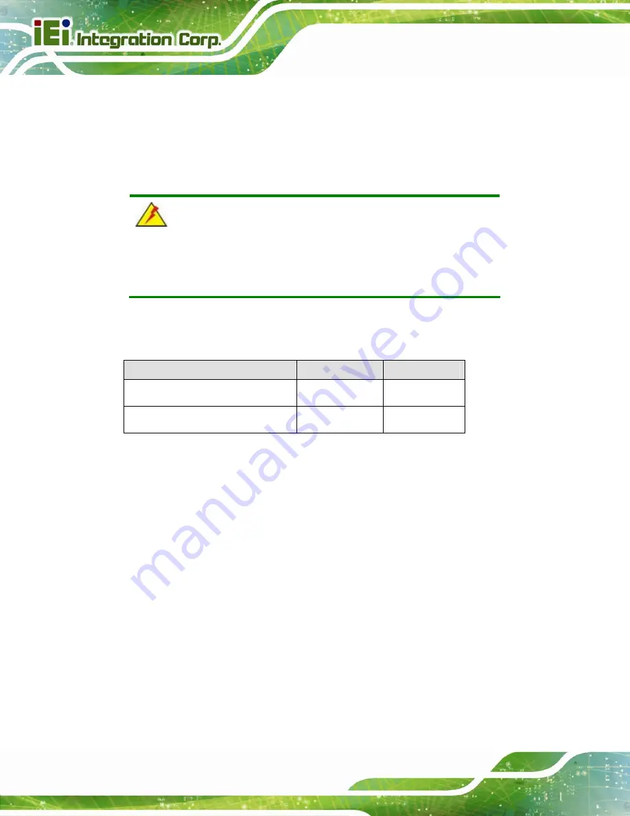
WARNING:
Do not change the settings on the jumpers in described here. Doing so
may disable or damage the system.
The following jumpers are preconfigured for the UPC-12A/GM45. Users should
NOT
change these jumpers.
Jumper Name
Label
Type
LVDS voltage selection
JP3
6-pin header
Panel Type and Resolution
JP1
8-pin header
Table 4-2: Preconfigured Jumpers
4.9.3 CF Voltage Select
Jumper Label:
JP7
Jumper Type:
3-pin header
Jumper Settings:
See
547H547H547H547H547H547H547H549H
Table 4-3
Jumper Location:
See
548H548H548H548H548H548H548H550H
Figure 4-10
The CF Voltage Select jumper sets the CF Type II slot can be set as 5 V or +3.3 V.
CF Voltage Select jumper settings are shown in
549H549H549H549H549H549H549H551H
Table 4-3
.
Summary of Contents for UPC-12A/GM45
Page 13: ...UPC 12A GM45 Panel PC Page 1 1 Introduction Chapter 1 ...
Page 24: ...UPC 12A GM45 Panel PC Page 12 2 Detailed Specifications Chapter 2 ...
Page 39: ...UPC 12A GM45 Panel PC Page 27 3 Unpacking Chapter 3 ...
Page 43: ...UPC 12A GM45 Panel PC Page 31 4 Installation Chapter 4 ...
Page 68: ...UPC 12A GM45 Panel PC Page 56 5 System Maintenance Chapter 5 ...
Page 76: ...UPC 12A GM45 Panel PC Page 64 6 AMI BIOS Setup Chapter 6 ...
Page 111: ...UPC 12A GM45 Panel PC Page 99 7 Battery Monitoring and Remote Control Chapter 7 ...
Page 127: ...UPC 12A GM45 Panel PC Page 115 A External Connector Pinouts Appendix A ...
Page 131: ...UPC 12A GM45 Panel PC Page 119 B Safety Precautions Appendix B ...
Page 136: ...UPC 12A GM45 Panel PC Page 124 C BIOS Configuration Options Appendix C ...
Page 139: ...UPC 12A GM45 Panel PC Page 127 D Watchdog Timer Appendix D ...
Page 142: ...UPC 12A GM45 Panel PC Page 130 E Hazardous Materials Disclosure Appendix E ...


