UPC-12A/GM45 Panel PC
Page 49
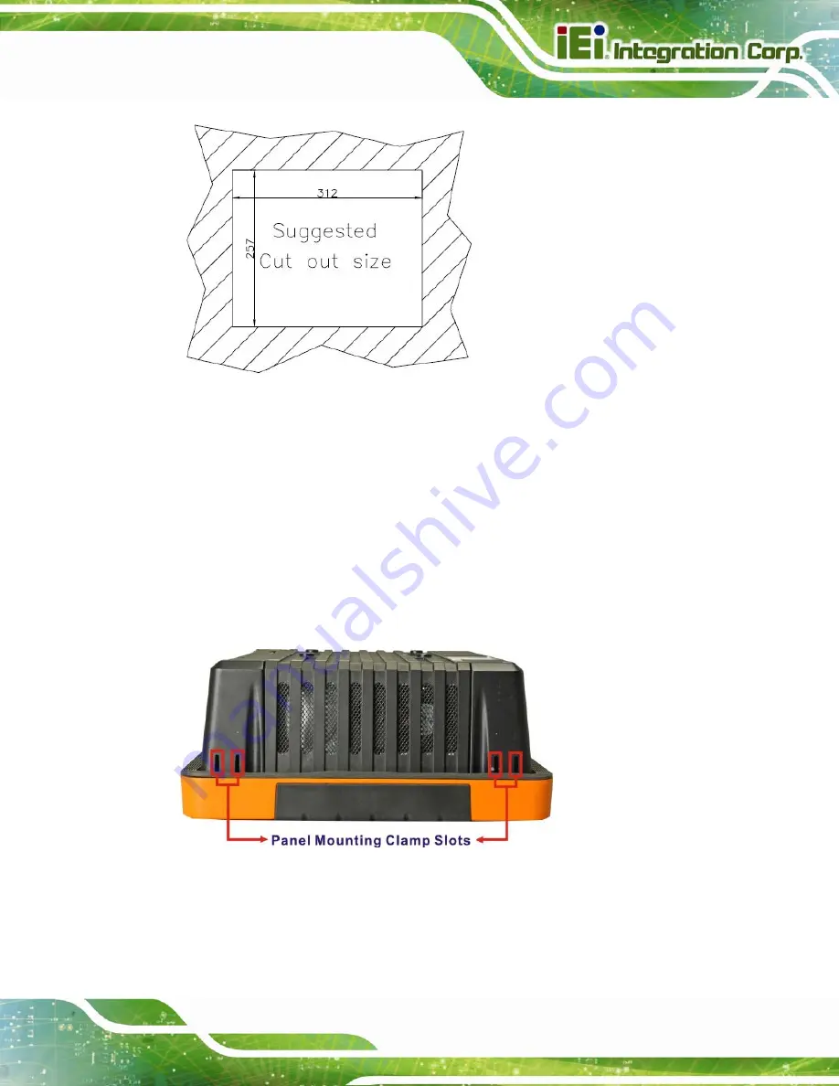
Figure 4-17: Suggested Panel Cut Out Size for UPC-12A/GM45 (Unit: mm)
Step 3:
Slide the flat panel computer through the previously cut hole. The chassis at the
rear of the flat panel should slide easily through the hole. Only stop sliding the
panel through the hole when the back of the front aluminum frame is flush
against the panel.
Step 4:
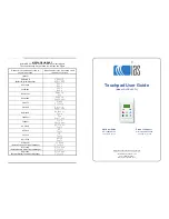
Insert the panel mounting clamps into the pre-formed holes along the edges of
the chassis, behind the aluminum frame. There are a total of 6 panel mounting
clamps for UPC-12A/GM45.
Figure 4-18: Panel Mounting Clamp Slots (Side View)
Summary of Contents for UPC-12A/GM45
Page 13: ...UPC 12A GM45 Panel PC Page 1 1 Introduction Chapter 1 ...
Page 24: ...UPC 12A GM45 Panel PC Page 12 2 Detailed Specifications Chapter 2 ...
Page 39: ...UPC 12A GM45 Panel PC Page 27 3 Unpacking Chapter 3 ...
Page 43: ...UPC 12A GM45 Panel PC Page 31 4 Installation Chapter 4 ...
Page 68: ...UPC 12A GM45 Panel PC Page 56 5 System Maintenance Chapter 5 ...
Page 76: ...UPC 12A GM45 Panel PC Page 64 6 AMI BIOS Setup Chapter 6 ...
Page 111: ...UPC 12A GM45 Panel PC Page 99 7 Battery Monitoring and Remote Control Chapter 7 ...
Page 127: ...UPC 12A GM45 Panel PC Page 115 A External Connector Pinouts Appendix A ...
Page 131: ...UPC 12A GM45 Panel PC Page 119 B Safety Precautions Appendix B ...
Page 136: ...UPC 12A GM45 Panel PC Page 124 C BIOS Configuration Options Appendix C ...
Page 139: ...UPC 12A GM45 Panel PC Page 127 D Watchdog Timer Appendix D ...
Page 142: ...UPC 12A GM45 Panel PC Page 130 E Hazardous Materials Disclosure Appendix E ...


