UPC-12A/GM45 Panel PC
Page 61
Step 2:
Turn off the power
. See
Section
585H585H585H585H584H584H584H586H
5.3
.
Step 3:
Remove the internal aluminum chassis
. See
Section
585H585H585H587H
5.4.3
.
Step 4:
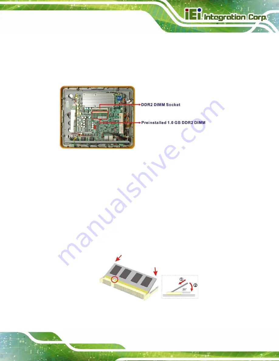
Locate the SO-DIMM module
. The SO-DIMM module is located below the CPU
heat sink. See
587H587H587H587H586H586H586H588H
Figure 5-3
.
Figure 5-3: SO-DIMM Socket Location
Step 5:
Open the SO-DIMM socket handles
. The SO-DIMM socket has two handles
that secure the SO-DIMM into the socket. Before the SO-DIMM can be removed
from the socket, the handles must be opened.
Step 6:
Align the SO-DIMM with the socket
. Align the notch on the memory with the
notch on the memory socket.
Step 7:
Insert the SO-DIMM
. Push the memory in at a 20º angle.
Step 8:
Seat the SO-DIMM
. Gently push downwards and the arms clip into place.
Step 0:
Figure 5-4: Installing a SO-DIMM
Summary of Contents for UPC-12A/GM45
Page 13: ...UPC 12A GM45 Panel PC Page 1 1 Introduction Chapter 1 ...
Page 24: ...UPC 12A GM45 Panel PC Page 12 2 Detailed Specifications Chapter 2 ...
Page 39: ...UPC 12A GM45 Panel PC Page 27 3 Unpacking Chapter 3 ...
Page 43: ...UPC 12A GM45 Panel PC Page 31 4 Installation Chapter 4 ...
Page 68: ...UPC 12A GM45 Panel PC Page 56 5 System Maintenance Chapter 5 ...
Page 76: ...UPC 12A GM45 Panel PC Page 64 6 AMI BIOS Setup Chapter 6 ...
Page 111: ...UPC 12A GM45 Panel PC Page 99 7 Battery Monitoring and Remote Control Chapter 7 ...
Page 127: ...UPC 12A GM45 Panel PC Page 115 A External Connector Pinouts Appendix A ...
Page 131: ...UPC 12A GM45 Panel PC Page 119 B Safety Precautions Appendix B ...
Page 136: ...UPC 12A GM45 Panel PC Page 124 C BIOS Configuration Options Appendix C ...
Page 139: ...UPC 12A GM45 Panel PC Page 127 D Watchdog Timer Appendix D ...
Page 142: ...UPC 12A GM45 Panel PC Page 130 E Hazardous Materials Disclosure Appendix E ...


