UPC-F12C-ULT3 Panel PC
Page 21
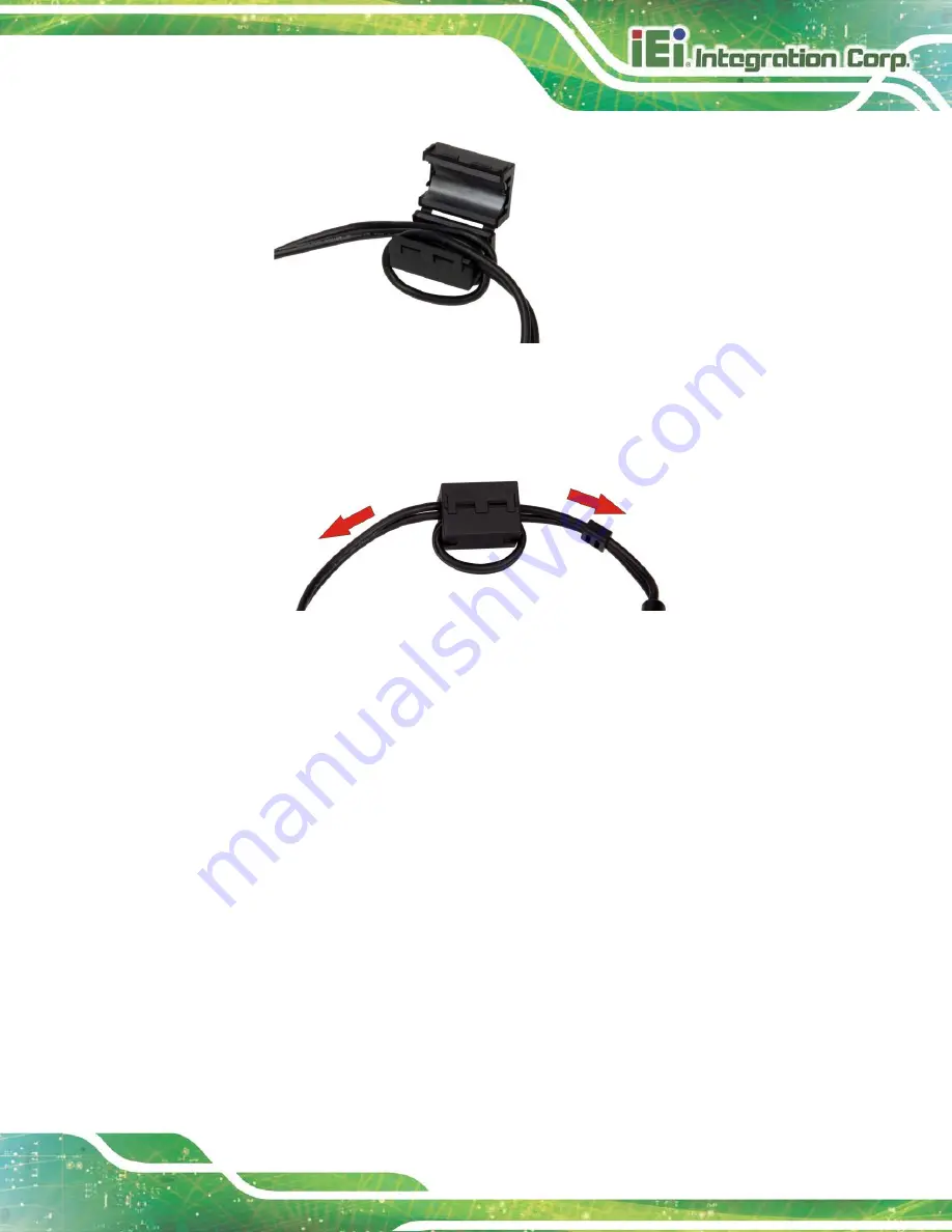
Figure 3-8: Wrapping Cable around the Core
Step 3:
Close the ferrite core and snap the latch back together. Then, pull both ends of
the cable in opposite direction to tighten the loop.
Step 0:
Figure 3-9: Cable Installed with Ferrite Core
3.6 Protection Grommet Installation
The UPC-F12C-ULT3 panel PC is shipped with several protection grommets which can be
used to protect the I/O panel from water intrusion. To install the grommet, follow the steps
below.
Step 1:
Remove the top panel of the I/O cover by removing the seven retention screws
as shown below.
Step 2:
Remove the I/O cover by removing the six retention screws as shown below.
Summary of Contents for UPC-F12C-ULT3
Page 15: ...UPC F12C ULT3 Panel PC Page 1 1 Introduction Chapter 1 ...
Page 23: ...UPC F12C ULT3 Panel PC Page 9 2 Unpacking Chapter 2 ...
Page 27: ...UPC F12C ULT3 Panel PC Page 13 3 Installation Chapter 3 ...
Page 43: ...UPC F12C ULT3 Panel PC Page 29 4 BIOS Setup Chapter 4 ...
Page 75: ...UPC F12C ULT3 Panel PC Page 61 Chapter 5 5 Interface Connectors ...
Page 95: ...UPC F12C ULT3 Panel PC Page 81 Appendix A A Regulatory Compliance ...
Page 100: ...UPC F12C ULT3 Panel PC Page 86 B Safety Precautions Appendix B ...
Page 106: ...UPC F12C ULT3 Panel PC Page 92 C BIOS Menu Options Appendix C ...
Page 109: ...UPC F12C ULT3 Panel PC Page 95 Appendix D D Watchdog Timer ...
Page 112: ...UPC F12C ULT3 Panel PC Page 98 Appendix E E Hazardous Materials Disclosure ...


