background image


WAFER-8523 User Manual 

Page 51

Chapter 

Installation 

Summary of Contents for WAFER-8523

Page 1: ...WAFER 8523 User Manual Page i WAFER 8523 MODEL WAFER 8523 3 5 SBC with Intel Celeron M CPU with VGA LVDS TTL GbE USB 2 0 and Audio Rev 1 01 24 July 2009 User Manual...

Page 2: ...WAFER 8523 User Manual Page ii Revision Date Version Changes 24 July 2009 1 01 Minor edit 14 April 2009 1 00 Initial release...

Page 3: ...s arising out of the use or inability to use the product or documentation even if advised of the possibility of such damages This document contains proprietary information protected by copyright All r...

Page 4: ...s representative directly To contact an IEI sales representative please send an email to sales iei com tw The items listed below should all be included in the WAFER 8523 package 1 x WAFER 8523 1 x SAT...

Page 5: ...LOW 10 2 4 COMPATIBLE PROCESSORS 10 2 4 1 CPU Overview 10 2 4 2 Preinstalled Intel Celeron M Processors 11 2 5 INTEL 852GM NORTHBRIDGE CHIPSET 11 2 5 1 Intel 852GM Overview 11 2 5 2 Intel 852GM Memory...

Page 6: ...onitoring 19 2 9 2 Operating Temperature and Temperature Control 20 2 9 3 Power Consumption 20 3 UNPACKING 21 3 1 ANTI STATIC PRECAUTIONS 22 3 2 UNPACKING 22 3 2 1 Unpacking Precautions 22 3 3 UNPACKI...

Page 7: ...4 4 4 Serial Port Connector COM1 48 4 4 5 VGA Connector 49 5 INSTALLATION 51 5 1 ANTI STATIC PRECAUTIONS 52 INSTALLATION CONSIDERATIONS 52 5 1 1 Installation Notices 53 5 1 2 Installation Checklist 53...

Page 8: ...ction 74 6 BIOS SCREENS 76 6 1 INTRODUCTION 77 6 1 1 Starting Setup 77 6 1 2 Using Setup 77 6 1 3 Getting Help 78 6 1 4 Unable to Reboot After Configuration Changes 78 6 1 5 BIOS Menu Bar 78 6 2 MAIN...

Page 9: ...DRIVER INSTALLATION 123 7 6 USB DRIVER INSTALLATION 125 7 7 AUDIO DRIVER INSTALLATION 129 7 7 1 AC 97 Driver Installation 129 7 8 ISMM INSTALLATION 132 A BIOS OPTIONS 139 B TERMINOLOGY 143 C WATCHDOG...

Page 10: ...nout Locations 31 Figure 4 6 CF Card Socket Location solder side 32 Figure 4 7 12V Fan Connector Location 34 Figure 4 8 IR Sensor Connector Location 35 Figure 4 9 LED Connector Locations 35 Figure 4 1...

Page 11: ...Cable Connection 71 Figure 5 15 PS 2 Keyboard Mouse Connector 72 Figure 5 16 LAN Connection 73 Figure 5 17 Serial Device Connector 74 Figure 5 18 VGA Connector 75 Figure 7 1 Start Up Screen 114 Figure...

Page 12: ...Audio 130 Figure 7 26 AC 97 Audio Driver Options 130 Figure 7 27 AC 97 Driver Installation Welcome Screen 131 Figure 7 28 AC 97 Driver Installation Verification 131 Figure 7 29 AC 97 Driver Installat...

Page 13: ...Connector Pinouts 36 Table 4 10 LVDS LCD Port Connector Pinouts 37 Table 4 11 PC 104 Connector Pinouts 1 of 2 38 Table 4 12 PC 104 Connector Pinouts 2 of 2 39 Table 4 13 PC 104 Power Input Connector...

Page 14: ...ings 59 Table 5 4 Clear CMOS Jumper Settings 61 Table 5 5 COM 2 Function Select Jumper Settings 62 Table 5 6 CRT LCD Mode Select Jumper Settings 63 Table 5 7 LVDS Voltage Selection Jumper Settings 64...

Page 15: ...Configuration 92 Menu 9 Advanced Power Configuration 93 Menu 10 Advanced Power Management Configuration 93 Menu 11 Remote Access Configuration Advanced 96 Menu 12 USB Configuration 99 Menu 13 PCI PnP...

Page 16: ...WAFER 8523 User Manual Page 1 Chapter 1 1 Introduction...

Page 17: ...zero KB cache The WAFER 8523 also includes 1 0 GB DDR SDRAM preinstalled The board comes with an LVDS connector and supports both 18 bit and 36 bit single channel LVDS screens The WAFER 8523 also com...

Page 18: ...WAFER 8523 User Manual Page 3 Figure 1 2 WAFER 8523 Overview Front View Figure 1 3 WAFER 8523 Overview Rear View...

Page 19: ...VDS connector 1 x PC 104 ISA connector 1 x Power button connector 1 x Reset button connector 1 x RS 232 serial port connector 1 x Serial ATA SATA drive connector 1 x USB 2 0 connector supports two USB...

Page 20: ...mpactFlash One CompactFlash Type II socket Super I O ITE IT8718 Display 18 bit dual channel LVDS integrated in Intel 825GM Dual display supported VGA and LVDS BIOS AMI BIOS Audio Realtek ALC655 AC 97...

Page 21: ...ption 5V 2 93A Intel Celeron M 1GHz Zero Cache Processor 512MB DDR DRAM 5V 2 57A Intel Celeron M 600MHz 512MB Cache Processor 512MB DDR DRAM Temperature 0 C 60 C 32 F 140 F Humidity operating 5 95 non...

Page 22: ...WAFER 8523 User Manual Page 7 Chapter 2 2 Detailed Specifications...

Page 23: ...ter describes the specifications and on board features of the WAFER 8523 in detail 2 2 Dimensions 2 2 1 Board Dimensions The dimensions of the board are listed below and shown in Figure 2 1 Length 146...

Page 24: ...AFER 8523 User Manual Page 9 2 2 2 External Interface Panel Dimensions External peripheral interface connector panel dimensions are shown in Figure 2 2 Figure 2 2 External Interface Panel Dimensions m...

Page 25: ...board chipsets and other components installed on the motherboard and described in the following sections of this chapter Figure 2 3 Data Flow Block Diagram 2 4 Compatible Processors 2 4 1 CPU Overvie...

Page 26: ...atforms It provides the processor interface system memory interface DDR SDRAM Hub interface CRT LVDS and one DVO port An ACPI compliant Intel 852GM chipset platform can support the Full On S0 Power On...

Page 27: ...aphics Controller The Intel 852GM has a graphics controller integrated into the chipset Some of the features of the Intel 852GM Integrated Graphics Controller are listed below Graphics Core Frequency...

Page 28: ...data format of 18 bpp o LCD panel power sequencing compliant with SPWG timing specification o Compliant with ANSI TIA EIA 644 1995 spec o Integrated PWM interface for LCD backlight inverter control o...

Page 29: ...omplies with AC 97 Component Specification Version 2 3 The AC 97 controller is connected to the onboard audio connector The audio connector is connected to an optional 5 1 channel or 7 1 channel audio...

Page 30: ...6 Intel ICH4 USB Controller Up to six high speed full speed or low speed USB devices are supported by the ICH4 High speed USB 2 0 with data transfers of up to 480Mb s is enabled with the ICH4 integrat...

Page 31: ...PC PCI DMA Controller Distributed DMA Controller ISA Interface SM Bus One analog line level mono output MONO_OUT Power on Serial Bus Configuration Serial IRQ Optional FLASH ROM Interface Versatile po...

Page 32: ...e listed below AMI Flash BIOS SMIBIOS DMI compliant Console redirection function support PXE Pre boot Execution Environment support USB booting support 2 8 3 iTE IT8718F Super I O chipset The iTE IT87...

Page 33: ...f programmable LED blinking periods 2 8 3 4 Super I O Enhanced Hardware Monitor The Super I O Enhanced Hardware Monitor monitors three thermal inputs VBAT internally and eight voltage monitor inputs T...

Page 34: ...lel Port EPP and the Extended Capabilities Port ECP modes 2 9 Environmental and Power Specifications 2 9 1 System Monitoring Three thermal inputs on the WAFER 8523 Super I O Enhanced Hardware Monitor...

Page 35: ...side of the heat sink before it is mounted on the CPU A heat sink is also mounted on the Northbridge chipset to ensure the operating temperature of the chip remains low 2 9 3 Power Consumption Table 2...

Page 36: ...WAFER 8523 User Manual Page 21 Chapter 3 3 Unpacking...

Page 37: ...wristband can help to prevent ESD from damaging the board Self grounding Before handling the board touch any grounded conducting material During the time the board is handled frequently touch any con...

Page 38: ...was purchased from or contact an IEI sales representative directly by sending an email to 2sales iei com tw 3 3 1 Package Contents The WAFER 8523 is shipped with the following components Quantity Item...

Page 39: ...lation Guide 3 3 2 Optional Items The following components are optional for WAFER 8523 Item and Part Number Image ATX power cable P N 32100 052100 RS LPT Cable P N 32200 015100 RS RS 232 422 485 cable...

Page 40: ...WAFER 8523 User Manual Page 25 Chapter 4 4 Connectors...

Page 41: ...erface connector locations Section 4 2 lists all the peripheral interface connectors seen in Section 4 1 1 4 1 1 WAFER 8523 Layout 6Figure 4 1 and Figure 4 2 show the on board peripheral connectors re...

Page 42: ...ctor Type Label ATX power connector 4 pin ATX CN6 Audio connector 10 pin header CN18 Backlight inverter connector 5 pin wafer CN5 Battery connector 2 pin wafer CN15 CompactFlash socket 50 pin CF socke...

Page 43: ...ors on the WAFER 8523 Detailed descriptions of these connectors can be found in Section 4 4 on page 645 Connector Type Label Ethernet connector RJ 45 CN19 Keyboard Mouse connector PS 2 CN20 LAN Active...

Page 44: ...Type 4 pin AT power connector 1x4 CN Location See Figure 4 3 CN Pinouts See Table 4 3 The 4 pin ATX power connector is connected to an ATX power supply Figure 4 3 ATX Power Connector Location PIN NO...

Page 45: ...io connector is connected to external audio devices including speakers and microphones for the input and output of audio signals to and from the system Figure 4 4 Audio Connector Pinouts 10 pin PIN NO...

Page 46: ...4 5 CN Pinouts See Table 4 5 The backlight inverter connectors provide the backlights on the LCD display connected to the WAFER 8523 with 12V of power Figure 4 5 Panel Backlight Connector Pinout Locat...

Page 47: ...ure 4 6 CN Pinouts See Table 4 6 A CF Type I or Type II memory card is inserted to the CF socket on the solder side of the WAFER 8523 Figure 4 6 CF Card Socket Location solder side PIN NO DESCRIPTION...

Page 48: ...8 D9 24 IOCS16 49 D10 25 CD2 50 GND2 Table 4 6 CF Card Socket Pinouts 4 3 5 Fan Connector 12V 3 pin CN Label CN1 CN Type 3 pin header CN Location See 7Figure 4 7 CN Pinouts See 7Table 4 7 The cooling...

Page 49: ...N 1 Fan Speed Detect 2 12V 3 GND Table 4 7 12V Fan Connector Pinouts 4 3 6 IR Sensor Connector CN Label CN13 CN Type 5 pin wafer connector CN Pinouts See Table 4 8 CN Location See Figure 4 8 The IR se...

Page 50: ...4 3 7 LED Connector CN Label CN17 CN Type 6 pin wafer 1x6 CN Location See Figure 4 9 CN Pinouts See Table 4 9 The LED connector connects to an HDD indicator LED and a power LED on the system chassis...

Page 51: ...Table 4 9 LED Connector Pinouts 4 3 8 LVDS LCD Connector CN Label CN3 CN Type 30 pin crimp 2x10 CN Location See 7Figure 4 10 CN Pinouts See 7Table 4 10 The 30 pin LVDS LCD connector can be connected...

Page 52: ...B_Y1 18 B_Y1 19 B_Y2 20 B_Y2 21 B_CK 22 B_CK 23 B_Y3 24 B_Y3 25 GND5 26 GND6 27 VCC_LCD 28 VCC_LCD 29 VCC_LCD 30 VCC_LCD Table 4 10 LVDS LCD Port Connector Pinouts 4 3 9 PC 104 Connector CN Label CN1...

Page 53: ...B20 BCLK A5 SD4 A21 SA10 B5 NC B21 IRQ7 A6 SD3 A22 SA9 B6 DRQ2 B22 IRQ6 A7 SD2 A23 SA8 B7 NC B23 IRQ5 A8 SD1 A24 SA7 B8 NOWS B24 IRQ4 A9 SD0 A25 SA6 B9 12V B25 IRQ3 A10 IOCHRDY A26 SA5 B10 GND B26 DAC...

Page 54: ...12 D6 IRQ12 D16 DRQ7 C7 SA19 C17 SD13 D7 IRQ15 D17 VCC C8 SA18 C18 SD14 D8 IRQ14 D18 MASTER C9 SA17 C19 SD15 D9 DACK0 D19 GND C10 MEMR C20 NC D10 DRQ0 D20 GND Table 4 12 PC 104 Connector Pinouts 2 of...

Page 55: ...CN Label CN7 CN Type 2 pin wafer 1x2 CN Location See Figure 4 13 CN Pinouts See Table 4 14 The power button connector is connected to a power switch on the system chassis to enable users to turn the...

Page 56: ...Figure 4 14 CN Pinouts See 7Table 4 15 The SATA drive connector can be connected to a first generation SATA drive First generation SATA drives transfer data at speeds as high as 150Mb s Figure 4 14 SA...

Page 57: ...an RS 232 serial communication channel but with the COM2 function select jumper can be configured as either an RS 422 or RS 485 serial communications channel Figure 4 15 COM2 Connector Pinout Location...

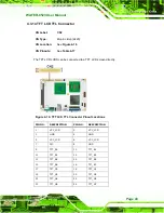
Page 58: ...LVDS can be connected to a TFT LCD screen directly Figure 4 16 TFT LCD TTL Connector Pinout Locations PIN NO DESCRIPTION PIN NO DESCRIPTION 1 VCC_LCD 2 VCC_LCD 3 GND 4 GND 5 VCC_LCD 6 VCC_LCD 7 N C 8...

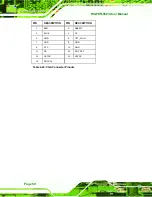
Page 59: ...39 N C 40 L_VDDEN Table 4 17 TFT LCD TTL Port Connector Pinouts 4 3 15 USB Connector Internal CN Label CN11 CN Type 9 pin header 2x4 CN Location See 7Figure 4 17 CN Pinouts See 7Table 4 18 The 9 pin U...

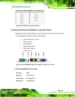
Page 60: ...the WAFER 8523 external peripheral interface connector EPIC panel The WAFER 8523 EPIC panel consists of the following 1 x Keyboard Mouse connector 1 x LAN connector 1 x LED indicator 1 x Reset button...

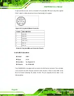
Page 61: ...TA 3 GROUND 4 VCC 5V 5 KB CLK 6 MS CLK Table 4 19 Keyboard Mouse Connector Pinouts 4 4 2 LAN Connectors CN Label CN19 CN Type RJ 45 CN Location See 7Figure 4 18 CN Pinouts See 7Table 4 20 The WAFER 85...

Page 62: ...een and one yellow The green LED indicates activity on the port and the yellow LED indicates the port is linked See 7Table 4 21 STATUS DESCRIPTION STATUS DESCRIPTION GREEN Activity YELLOW Linked Table...

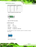
Page 63: ...set Switch 2 GND Table 4 22 Reset Button Connector Pinouts 4 4 4 Serial Port Connector COM1 CN Label CN21 CN Type DB 9 connectors CN Location See 7Figure 4 18 see 2 CN Pinouts See 7Table 4 23 and 7Fig...

Page 64: ...4 23 RS 232 Serial Port COM 1 Pinouts Figure 4 22 COM1 Pinout Locations 4 4 5 VGA Connector CN Label CN22 CN Type 15 pin Female CN Location See 7Figure 4 18 CN Pinouts See 7Figure 4 23 and 7Table 4 2...

Page 65: ...R 8523 User Manual Page 50 PIN DESCRIPTION PIN DESCRIPTION 1 RED 2 GREEN 3 BLUE 4 NC 5 GND 6 CRT_PLUG 7 GND 8 GND 9 VCC 10 GND 11 NC 12 DDC DAT 13 HSYNC 14 VSYNC 15 DDCCLK Table 4 24 VGA Connector Pin...

Page 66: ...WAFER 8523 User Manual Page 51 Chapter 5 5 Installation...

Page 67: ...vent ESD from damaging the board Self grounding Before handling the board touch any grounded conducting material During the time the board is handled frequently touch any conducting materials that are...

Page 68: ...damage Place the WAFER 8523 on an antistatic pad o When installing or configuring the motherboard place it on an antistatic pad This helps to prevent potential ESD damage Turn all power to the WAFER 8...

Page 69: ...he following devices are properly connected o SATA drives o Power supply o USB cable o Serial port cable o PS 104 modules The following external peripheral devices are properly connected to the chassi...

Page 70: ...are listed in Chapter 2 To install a SO DIMM into a SO DIMM socket please follow the steps below and refer to Figure 5 1 Figure 5 1 SO DIMM Installation Step 1 Locate the SO DIMM socket Place the WAFE...

Page 71: ...cards and CF Type II cards For the complete specifications of the supported CF cards please refer to Chapter 2 To install the CF card Type 1 or Type 2 onto the WAFER 8523 please follow the steps belo...

Page 72: ...sed to close an electrical circuit It consists of two metal pins and a small metal clip often protected by a plastic cover that slides over the pins to connect them To CLOSE SHORT a jumper means conne...

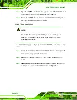
Page 73: ...type setting JP2 3 pin header LCD power setting JP1 3 pin header Table 5 1 Jumpers 5 4 1 AT ATX Power Select Jumper Settings NOTE The AT Power Select Jumper is the same as the ATX Enable connector Jum...

Page 74: ...AT ATX Power Select Jumper Location 5 4 2 CF Card Setup Jumper Label JP4 Jumper Type 3 pin header Jumper Settings See Table 5 3 Jumper Location See Figure 5 4 The CF Card Setup jumper sets the CF Typ...

Page 75: ...ar CMOS jumper clears the CMOS data and resets the system BIOS information To do this use the jumper cap to close pins 2 and 3 for a few seconds then reinstall the jumper clip back to pins 1 and 2 If...

Page 76: ...of the clear CMOS jumper is shown in 7Figure 5 5 below Figure 5 5 Clear CMOS Jumper 5 4 4 COM 2 Function Select Jumper Jumper Label JP5 Jumper Type 6 pin header Jumper Settings See Table 5 5 Jumper L...

Page 77: ...he COM 2 Function Select jumper location is shown in Figure 5 6 Figure 5 6 COM 2 Function Select Jumper Location 5 4 5 TTL LVDS LCD Mode Select Jumper Jumper Label JP2 Jumper Type 3 pin header Jumper...

Page 78: ...ure 5 7 Figure 5 7 TTL LVDS Mode Select Jumper Settings 5 4 6 LVDS Voltage Selection WARNING Permanent damage to the screen and WAFER 8523 may occur if the wrong voltage is selected with this jumper P...

Page 79: ...LCD Voltage Select Description Short 1 2 3 3V LVDS Default Short 2 3 5V LVDS Table 5 7 LVDS Voltage Selection Jumper Settings The LVDS Voltage Selection jumper location is shown in Figure 5 8 Figure...

Page 80: ...at 3sales iei com tw or visit the IEI website 3http www ieiworld com tw to find out more about the available chassis 5 5 1 Motherboard Installation To install the WAFER 8523 motherboard into the chass...

Page 81: ...he connectors The locations of the SATA drive connectors are shown in Chapter 3 Step 2 Insert the cable connector Press the clip on the connector at the end of the SATA cable and insert the cable conn...

Page 82: ...ive Connection 5 6 3 Dual RS 232 Cable Connection w o bracket Optional The dual RS 232 cable consists of two connectors attached to two independent cables Each cable is then attached to a D sub 9 pin...

Page 83: ...nstallation Step 3 Secure the connectors Both single RS 232 connectors have two retention screws that must be secured to a chassis or bracket Step 4 Connect the serial device Once the single RS 232 co...

Page 84: ...vides a stereo line level input to connect to the output of an audio device Line out a stereo line level output connects to two amplified speakers To install the audio kit please refer to the steps be...

Page 85: ...The WAFER 8523 is shipped with a dual port USB 2 0 cable To connect the USB cable connector please follow the steps below Step 1 Locate the connectors The locations of the USB connectors are shown in...

Page 86: ...chassis please refer to the installation instructions that came with the chassis Step 0 5 7 External Peripheral Interface Connection The following external peripheral devices can be connected to the e...

Page 87: ...t a keyboard and mouse to the WAFER 8523 Step 1 Locate the dual PS 2 connector The location of the PS 2 connector is shown in Chapter 3 Step 2 Insert the keyboard mouse connector Insert the PS 2 conne...

Page 88: ...wn in Chapter 4 Step 4 Align the connectors Align the RJ 45 connector on the LAN cable with one of the RJ 45 connector on the WAFER 8523 See 7Figure 5 16 Figure 5 16 LAN Connection Step 5 Insert the L...

Page 89: ...face by tightening the two retention screws on either side of the connector Step 0 5 7 4 VGA Monitor Connection The WAFER 8523 has a single female DB 15 connector on the external peripheral interface...

Page 90: ...sert the male connector from the VGA screen into the female connector on the WAFER 8523 See 7Figure 5 18 Figure 5 18 VGA Connector Step 4 Secure the connector Secure the DB 15 VGA connector from the V...

Page 91: ...WAFER 8523 User Manual Page 76 Chapter 6 6 BIOS Screens...

Page 92: ...ge appears on the screen 0 If the message disappears before the DELETE key is pressed restart the computer and try again 6 1 2 Using Setup Use the arrow keys to highlight items press ENTER to select u...

Page 93: ...Changes If the computer cannot boot after changes to the system configuration is made CMOS defaults Use the jumper described in Chapter 5 6 1 5 BIOS Menu Bar The menu bar on top of the BIOS screen ha...

Page 94: ...items shown in the system overview include AMI BIOS Displays auto detected BIOS information o Version Current BIOS version o Build Date Date the current BIOS version was made o ID Installed BIOS ID Pr...

Page 95: ...eripheral devices through the following sub menus WARNING Setting the wrong values in the sections below may cause the system to malfunction Make sure that the settings made are compatible with the ha...

Page 96: ...menu 873H788HBIOS Menu 3 to view detailed CPU specifications and configure the CPU BIOS Menu 3 CPU Configuration The CPU Configuration menu 874H789HBIOS Menu 3 lists the following CPU details Manufac...

Page 97: ...Menu 4 IDE Configuration ATA IDE Configurations Compatible Use the ATA IDE Configurations option to configure the ATA IDE controller Disabled Disables the on board ATA IDE controller Compatible Config...

Page 98: ...OS displays the status of the auto detected IDE devices The following IDE devices are detected and are shown in the IDE Configuration menu Primary IDE Master Primary IDE Slave Secondary IDE Master Sec...

Page 99: ...the device LBA Mode Indicates whether the LBA Logical Block Addressing is a method of addressing data on a disk drive is supported or not Block Mode Block mode boosts IDE drive performance by increas...

Page 100: ...CD DVD option specifies that an IDE CD ROM drive is attached to the specified IDE channel The BIOS does not attempt to search for other types of IDE disk drives on the specified channel ARMD This opt...

Page 101: ...g cycles between the IDE drive and the programmable IDE controller As the PIO mode increases the cycle time decreases Auto DEFAULT BIOS auto detects the PIO mode Use this value if the IDE disk drive s...

Page 102: ...MWDMA2 Multi Word DMA mode 2 selected with a maximum data transfer rate of 16 6MBps UDMA1 Ultra DMA mode 0 selected with a maximum data transfer rate of 16 6MBps UDMA1 Ultra DMA mode 1 selected with a...

Page 103: ...nts BIOS from using the HDD SMART feature Enabled Allows BIOS to use the HDD SMART feature 32Bit Data Transfer Enabled Use the 32Bit Data Transfer BIOS option to enables or disable 32 bit data transfe...

Page 104: ...option to select the Serial Port 2 base address Disabled No base address is assigned to Serial Port 2 2F8 IRQ3 DEFAULT Serial Port 2 I O port address is 3F8 and the interrupt address is IRQ3 3E8 IRQ4...

Page 105: ...e The ECP mode supports bi directional communication between the system and the parallel port device and the transmission rates between the two are much faster than the SPP mode EPP ECP The parallel p...

Page 106: ...lth Configuration The following system parameters and values are shown The system parameters that are monitored are System Temperatures The following system temperatures are monitored o System Tempera...

Page 107: ...ower modes This menu also displays the current AT ATX jumper setting BIOS Menu 8 Power Configuration When ATX power is selected the following menu appears 880H795HBIOS Menu 9 The Advanced Power Config...

Page 108: ...tion menu 797HBIOS Menu 10 allows the advanced power management options to be configured BIOS Menu 10 Advanced Power Management Configuration Restore on AC Power Loss Last State Use the Restore on AC...

Page 109: ...on Keyboard Mouse BIOS option to enable activity on either the keyboard or mouse to rouse the system from a suspend or standby state That is the system is roused when the mouse is moved or a button o...

Page 110: ...ed from a suspended state Disabled DEFAULT The real time clock RTC cannot generate a wake event Enabled If selected the following appears with values that can be selected RTC Alarm Date Days System Ti...

Page 111: ...ble access to the remote functionalities of the system Disabled DEFAULT Remote access is disabled Enabled Remote access configuration options shown below appear Serial Port Number Serial Port Mode Flo...

Page 112: ...listed above Serial Port Mode 115200 8 n 1 Use the Serial Port Mode option to select baud rate through which the console redirection is made The following configuration options are available 115200 8...

Page 113: ...terminal type is VT100 VT UTF8 The target terminal type is VT UTF8 VT UTF8 Combo Key Support Disabled Use the VT UFT8 Combo Key Support option to enable additional keys that are not provided by VT100...

Page 114: ...iguration Use the USB Configuration menu 883H799HBIOS Menu 12 to read USB configuration information and configure the USB settings BIOS Menu 12 USB Configuration USB Functions Enabled Use the USB Func...

Page 115: ...if this option is not enabled any attached USB mouse or USB keyboard does not become available until a USB compatible operating system is fully booted with all USB drivers loaded When this option is e...

Page 116: ...to specify what IRQs can be assigned to a particular peripheral device Available DEFAULT The specified IRQ is available to be used by PCI PnP devices Reserved The specified IRQ is reserved for use by...

Page 117: ...hannels are DM Channel 0 DM Channel 1 DM Channel 3 DM Channel 5 DM Channel 6 DM Channel 7 Reserved Memory Size Disabled Use the Reserved Memory Size BIOS option to specify the amount of memory that sh...

Page 118: ...ttings Configuration Use the Boot Settings Configuration menu 886H802HBIOS Menu 14 to configure advanced system boot options BIOS Menu 15 Boot Settings Configuration Quick Boot Enabled Use the Quick B...

Page 119: ...third party BIOS to display during system boot Keep Current Allows the computer system to display the information during system boot Bootup Num Lock Off The Bootup Num Lock BIOS option allows the Num...

Page 120: ...DEFAULT Cannot be booted from a remote system through the LAN Enabled DEFAULT Can be booted from a remote system through the LAN 6 5 2 Boot Device Priority Use the Boot Device Priority menu 887H803HB...

Page 121: ...ed select this field and enter the password After the password has been added Install appears next to Change Supervisor Password Change User Password Use the Change User Password to set or change a us...

Page 122: ...or the Chipset BIOS selections in the Chipset BIOS menu may cause the system to malfunction BIOS Menu 18 Chipset 6 7 1 Northbridge Chipset Configuration Use the Northbridge Chipset Configuration menu...

Page 123: ...that came with the card to see if it is necessary to reserve the space Disabled DEFAULT Memory is not reserved for ISA expansion cards 15MB 16MB Memory is reserved for ISA expansion cards Internal Gr...

Page 124: ...aperture 256MB 256MB of memory use for AGP aperture Boot Display Device Auto The Boot Display Device BIOS option selects the display device the system uses when it boots The available options are lis...

Page 125: ...isables the on board LAN controller Enabled The on board LAN controller is enabled Disabled DEFAULT The on board LAN controller is disabled Spread Spectrum Mode The Spread Spectrum Mode option enables...

Page 126: ...out saving the changes made to the system Discard Changes Use the Discard Changes option to discard the changes and remain in the BIOS configuration setup program Load Optimal Defaults Use the Load Op...

Page 127: ...WAFER 8523 User Manual Page 112 Chapter 7 7 Software Drivers...

Page 128: ...lled on the system 302H7 3 Chipset Driver Installation 809H115 303H7 4 VGA Driver Installation 810H118 304H7 5 LAN Driver Installation 811H123 305H7 6 USB Driver Installation 812H125 306H7 7 Audio Dri...

Page 129: ...R 8523 User Manual Page 114 Step 2 The screen in 815HFigure 7 1 appears Figure 7 1 Start Up Screen Step 3 Click WAFER 8523 Step 4 The list of drivers in 816HFigure 7 2 appears S t e p 0 Figure 7 2 Dri...

Page 130: ...1 Access the driver list shown in 817HFigure 7 2 See Section 818H7 2 Step 2 Click 1 Chipset Driver Step 3 When the setup files are completely extracted the Welcome Screen in 819HFigure 7 3 appears Fig...

Page 131: ...re 7 4 Chipset Driver License Agreement Step 6 Read the License Agreement Step 7 Click the YES button to accept the license agreement and continue Step 8 The Read Me file in 821HFigure 7 5 appears Fig...

Page 132: ...ck NEXT to continue Step 10 Setup Operations are performed as shown in 822HFigure 7 6 Figure 7 6 Chipset Driver Setup Operations Step 11 Once the Setup Operations are complete click the NEXT icon to c...

Page 133: ...nt to restart the computer now and click the Finish icon See 823HFigure 7 7 Step 0 7 4 VGA Driver Installation To install the VGA driver please do the following Step 1 Access the driver list shown in...

Page 134: ...119 Figure 7 8 VGA Driver Read Me File Step 4 Click NEXT to continue Step 5 The installation files are extracted See 827HFigure 7 9 Figure 7 9 VGA Driver Setup Files Extracted Step 6 The Welcome Scree...

Page 135: ...Manual Page 120 Figure 7 10 VGA Driver Welcome Screen Step 7 Click NEXT to continue Step 8 The license agreement in 829HFigure 7 11 appears Figure 7 11 VGA Driver License Agreement Step 9 Read the Li...

Page 136: ...ile in 830HFigure 7 12 appears Figure 7 12 VGA Driver Read Me File Step 12 Click NEXT to continue Step 13 Setup Operations are performed as shown in 831HFigure 7 13 NOTE The Found New Hardware Wizard...

Page 137: ...er Manual Page 122 Figure 7 13 VGA Driver Setup Operations Step 14 Once the Setup Operations are complete click NEXT to continue Step 15 The Finish screen appears Figure 7 14 VGA Driver Installation F...

Page 138: ...Installation To install the chipset driver please do the following Step 1 Access the driver list shown in 833HFigure 7 2 See Section 834H7 2 Step 2 Click 3 LAN Step 3 The Welcome screen in 835HFigure...

Page 139: ...to proceed with the installation Step 7 The program begins to install Step 8 The installation progress can be monitored in the progress bar shown in 837HFigure 7 17 Figure 7 17 LAN Driver Installatio...

Page 140: ...FINISH to exit the InstallShield Wizard 839HFigure 7 18 Step 0 7 6 USB Driver Installation To install the USB driver please do the following Step 1 Access the driver list shown in 840HFigure 7 2 See...

Page 141: ...l directory icon 843HFigure 7 19 Step 5 The contents of the directory are displayed 844HFigure 7 20 Figure 7 20 Operating System Directory Step 6 Choose the Operating System Double click the folder ic...

Page 142: ...Installation File Step 8 Double click the USB20 exe file icon 847HFigure 7 21 Step 9 When the setup files are completely extracted the Welcome Screen in 848HFigure 7 22 appears Figure 7 22 USB Driver...

Page 143: ...eement in 849HFigure 7 23 appears Figure 7 23 USB Driver License Agreement Step 12 Read the License Agreement Step 13 Click the YES button to accept the license agreement and continue Step 14 After se...

Page 144: ...r Installation There is no audio driver on the WAFER 8523 To add audio capabilities to the WAFER 8523 connect an AC 97 audio kit available from IEI Follow the installation instructions applicable to t...

Page 145: ...ER 8523 User Manual Page 130 Figure 7 25 AC 97 Audio Step 3 Browse to E 4 Audio ALC665 Windows Windows 98Gold 98se Me 2000 XP 2003 32 64 bits A3 84 853HFigure 7 26 Figure 7 26 AC 97 Audio Driver Optio...

Page 146: ...4HFigure 7 26 Step 5 The AC 97 Driver Installation screen in 855HFigure 7 27 appears Figure 7 27 AC 97 Driver Installation Welcome Screen Step 6 Click NEXT to continue Step 7 The Verification window i...

Page 147: ...ISH to exit the InstallShield Wizard and restart the computer Step 0 7 8 iSMM Installation The iSMM Intelligent System Management Module allows hardware functions to be monitored from within the opera...

Page 148: ...irectory Step 4 Double click the iSMM EN V1 11 00 directory icon 861HFigure 7 30 Step 5 The contents of the directory are displayed 862HFigure 7 31 Figure 7 31 iSMM Installation File Step 6 Double cli...

Page 149: ...7 The iSMM InstallShield Welcome Screen appears 864HFigure 7 32 Figure 7 32 iSMM InstallShield Welcome Screen Step 8 Click NEXT to continue Step 9 The License Agreement screen appears 865HFigure 7 33...

Page 150: ...XT to continue 867HFigure 7 33 Step 12 The Customer Information screen appears 868HFigure 7 34 Figure 7 34 iSMM Customer Information Step 13 Fill in the User Name and Organization fields which will be...

Page 151: ...WAFER 8523 User Manual Page 136 Step 15 The Setup Type screen appears 871HFigure 7 35 Figure 7 35 iSMM Setup Type Step 16 Select Complete 872HFigure 7 35 Step 17 Click NEXT to continue 873HFigure 7 35...

Page 152: ...523 User Manual Page 137 Step 18 The Installation Confirmation screen appears 874HFigure 7 36 Figure 7 36 iSMM Installation Confirmation Step 19 Click INSTALL to begin installing the drivers 875HFigur...

Page 153: ...6HFigure 7 37 Figure 7 37 iSMM InstallShield Wizard Complete Step 21 Click FINISH to exit the installation program 877HFigure 7 37 Step 22 The Restart Confirmation screen appears 878HFigure 7 38 Figur...

Page 154: ...WAFER 8523 User Manual Page 139 Appendix A A BIOS Options...

Page 155: ...e Auto 891H86 321H DMA Mode Auto 892H86 322H S M A R T Auto 893H88 323H 32Bit Data Transfer Enabled 894H88 324H Serial Port1 Address 3F8 IRQ4 895H89 325H Serial Port2 Address 2F8 IRQ3 896H89 326H Para...

Page 156: ...Legacy USB Support Enabled 926H100 356H IRQ Available 927H101 357H DMA Channel Available 928H102 358H Reserved Memory Size Disabled 929H102 359H Quick Boot Enabled 930H103 360H Quiet Boot Disabled 93...

Page 157: ...WAFER 8523 User Manual Page 142 376H Load Optimal Defaults 947H111 377H Load Failsafe Defaults 948H111...

Page 158: ...WAFER 8523 User Manual Page 143 Appendix B B Terminology...

Page 159: ...a binary 0 while a high amplitude signal represents a binary 1 BIOS The Basic Input Output System BIOS is firmware that is first run when the computer is turned on and can be configured by the end use...

Page 160: ...ency ratio and the processor core voltage FSB The Front Side Bus FSB is the bi directional communication channel between the processor and the Northbridge chipset GbE Gigabit Ethernet GbE is an Ethern...

Page 161: ...has transfer speeds up to 1 5 Gbps and the SATA II bus has data transfer speeds of up to 3 0 Gbps S M A R T Self Monitoring Analysis and Reporting Technology S M A R T refers to automatic status check...

Page 162: ...WAFER 8523 User Manual Page 147 Appendix C C Watchdog Timer...

Page 163: ...BIOS function call INT 15H is used to control the Watchdog Timer INT 15H AH 6FH Sub function AL 2 Sets the Watchdog Timer s period BL Time out value Its unit second is dependent on the item Watchdog...

Page 164: ...system resets EXAMPLE PROGRAM INITIAL TIMER PERIOD COUNTER W_LOOP MOV AX 6F02H setting the time out value MOV BL 30 time out value is 48 seconds INT 15H ADD THE APPLICATION PROGRAM HERE CMP EXIT_AP 1...

Page 165: ...WAFER 8523 User Manual Page 150 Appendix D D Compatibility...

Page 166: ...ting systems have been successfully run on the WAFER 8523 MS DOS 6 22 Microsoft Windows XP 32 bit Microsoft Windows 2000 Microsoft Vista Business 32 bit Fedora Core 6 Ubuntu 8 04 1 D 2 Compatible Proc...

Page 167: ...K4H510838D UCCC 512 MB 400 MHz DDR A DATA K4H511638C UC83 512 MB 333 MHz DDR Apacer AM3A5708B PK 5B0707D 512 MB 400 MHz DDR Apacer AM3A5708B PK 5B0717F 512 MB 400 MHz DDR DSL 534A HY5DU1216 22CTP D43K...

Page 168: ...WAFER 8523 User Manual Page 153 Appendix E E Hazardous Materials Disclosure...

Page 169: ...presences of small quantities of certain materials in the product and is applicable to China RoHS only A label will be placed on each product to indicate the estimated Environmentally Friendly Use Pe...

Page 170: ...t Board X O O O O X Metal Fasteners X O O O O O Cable Assembly X O O O O X Fan Assembly X O O O O X Power Supply Assemblies X O O O O X Battery O O O O O O O This toxic or hazardous substance is conta...

Page 171: ...WAFER 8523 User Manual Page 156 RoHS RoHS Pb Hg Cd CR VI PBB PBDE X O O O O X X O O O O X X O O O O X X O O O O O X O O O O X X O O O O X X O O O O X O O O O O O O SJ T11363 2006 X SJ T11363 2006...

Page 172: ...WAFER 8523 User Manual Page 157 Index...

Page 173: ...inverter connector 4 31 location and pinouts 31 BIOS 77 78 79 80 81 82 83 84 88 91 92 93 95 96 98 99 100 101 102 103 104 105 106 107 108 109 110 111 C cables 65 dual port USB 70 dual RS 232 67 SATA d...

Page 174: ...power button 40 reset button 47 serial port COM3 to COM6 42 TFT LCD LVDS 40 pin 43 USB internal 44 cooling 64 airflow 64 cooling fan 33 91 CPU 11 compatible 11 CRT 109 D Data Flow Block Diagram 10 DB...

Page 175: ...onnector 4 keyboard controller 18 L LAN connection 73 LAN connector 46 LCD display 31 backlight inverter connector 31 LED HDD indicator 35 power status 35 LED connector 4 35 HDD indicator LED connecto...

Page 176: ...ect jumper 58 ATX power supply 29 power LED 35 processors 11 R real time clock 15 reset button connector 4 RJ 45 connection 73 single connector 73 RJ 45 connector 46 RJ 45 connector 47 RJ 45 Ethernet...

Page 177: ...erature 91 TFT LCD LVDS connector 40 pin 43 location and pinouts 43 U unpacking 22 unpacking checklist 23 unpacking precautions 22 USB 44 45 70 99 100 cable dual port 70 cable 70 cable 70 cable connec...

Reviews: