WAFER-CV-D25501/N26001 3.5" SBC
Page 18
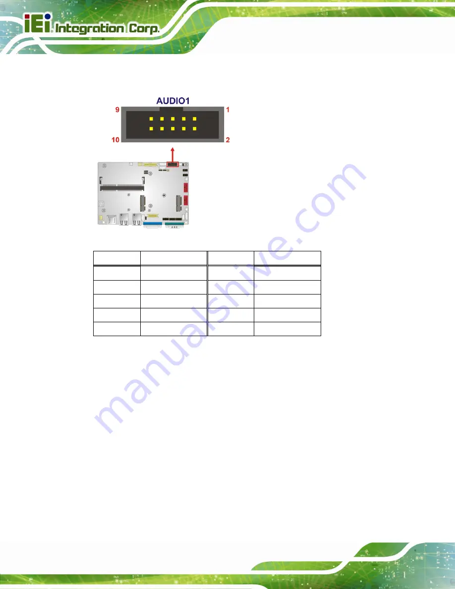
The 10-pin audio connector is connected to external audio devices including speakers and
microphones for the input and output of audio signals to and from the system.
Figure 3-4: Audio Connector Location
Pin Description
Pin Description
1
Line-out_R
2
Line-in_R
3
AUD_GND
4
AUD_GND
5
Line-out _L
6
Line-in _L
7
AUD_GND
8
AUD_GND
9
MIC1_R
10
MIC1_L
Table 3-5: Audio Connector Pinouts
3.2.4 Backlight Inverter Connectors
CN Label:
INV1
,
INV2
CN Type:
5-pin wafer
CN Location:
CN Pinouts:
The backlight inverter connectors provide the backlights on the LCD display connected to
the WAFER-CV-D25501/N26001 with +12V of power.
Summary of Contents for WAFER-CV-D25501
Page 11: ...WAFER CV D25501 N26001 3 5 SBC Page xi Figure 6 18 Audio Driver Installation Complete 103...
Page 15: ...WAFER CV D25501 N26001 3 5 SBC Page 1 Chapter 1 1 Introduction...
Page 19: ...WAFER CV D25501 N26001 3 5 SBC Page 5 Figure 1 3 WAFER CV D25501 N26001 Dimensions mm...
Page 23: ...WAFER CV D25501 N26001 3 5 SBC Page 9 Chapter 2 2 Packing List...
Page 27: ...WAFER CV D25501 N26001 3 5 SBC Page 13 Chapter 3 3 Connectors...
Page 52: ...WAFER CV D25501 N26001 3 5 SBC Page 38 Chapter 4 4 Installation...
Page 75: ...WAFER CV D25501 N26001 3 5 SBC Page 61 Chapter 5 5 BIOS...
Page 103: ...WAFER CV D25501 N26001 3 5 SBC Page 89 6 Software Drivers Chapter 6...
Page 118: ...WAFER CV D25501 N26001 3 5 SBC Page 104 Appendix A A Regulatory Compliance...
Page 120: ...WAFER CV D25501 N26001 3 5 SBC Page 106 Appendix B B BIOS Options...
Page 123: ...WAFER CV D25501 N26001 3 5 SBC Page 109 Appendix C C Terminology...
Page 127: ...WAFER CV D25501 N26001 3 5 SBC Page 113 Appendix D D Digital I O Interface...
Page 130: ...WAFER CV D25501 N26001 3 5 SBC Page 116 Appendix E E Watchdog Timer...
Page 133: ...WAFER CV D25501 N26001 3 5 SBC Page 119 Appendix F F Hazardous Materials Disclosure...


