WAFER-PV-D5252/D4252/N4552 SBC
Page 23
CN Pinouts:
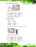
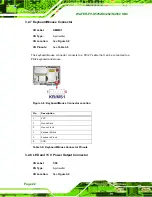
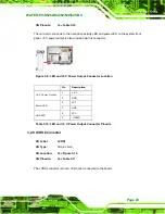
The connector connects to the hard drive activity LED and power LED on the system front
panel. +5 V power output is also provided via this connector.
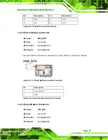
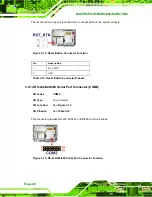
Figure 3-9: LED and +5 V Power Output Connector Location
Pin
Description
1 +5
V
+5 V Power Output
2 GND
3 VCC
Power LED
4 GND
5 VCC
HDD LED
6 -HDLED
Table 3-10: LED and +5 V Power Output Connector Pinouts
3.2.9 LVDS Connector
CN Label:
LVDS1
CN Type:
30-pin crimp
CN Location:
CN Pinouts:
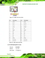
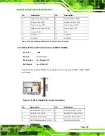
The LVDS connector is for an LCD panel connected to the board.
Summary of Contents for WAFER-PV-D4252
Page 14: ...WAFER PV D5252 D4252 N4552 SBC Page 1 Chapter 1 1 Introduction...
Page 18: ...WAFER PV D5252 D4252 N4552 SBC Page 5 Figure 1 4 Dimensions with Heatsink mm...
Page 22: ...WAFER PV D5252 D4252 N4552 SBC Page 9 Chapter 2 2 Packing List...
Page 26: ...WAFER PV D5252 D4252 N4552 SBC Page 13 Chapter 3 3 Connector Pinouts...
Page 52: ...WAFER PV D5252 D4252 N4552 SBC Page 39 Chapter 4 4 Installation...
Page 76: ...WAFER PV D5252 D4252 N4552 SBC Page 63 Chapter 5 5 BIOS...
Page 104: ...WAFER PV D5252 D4252 N4552 SBC Page 91 Appendix A A BIOS Options...
Page 107: ...WAFER PV D5252 D4252 N4552 SBC Page 94 Appendix B B One Key Recovery...
Page 135: ...WAFER PV D5252 D4252 N4552 SBC Page 122 Appendix C C Terminology...
Page 139: ...WAFER PV D5252 D4252 N4552 SBC Page 126 Appendix D D Hazardous Materials Disclosure...


