WAFER-PV-D5252/D4252/N4552 SBC
Page 35
3.3 External Interface Connectors
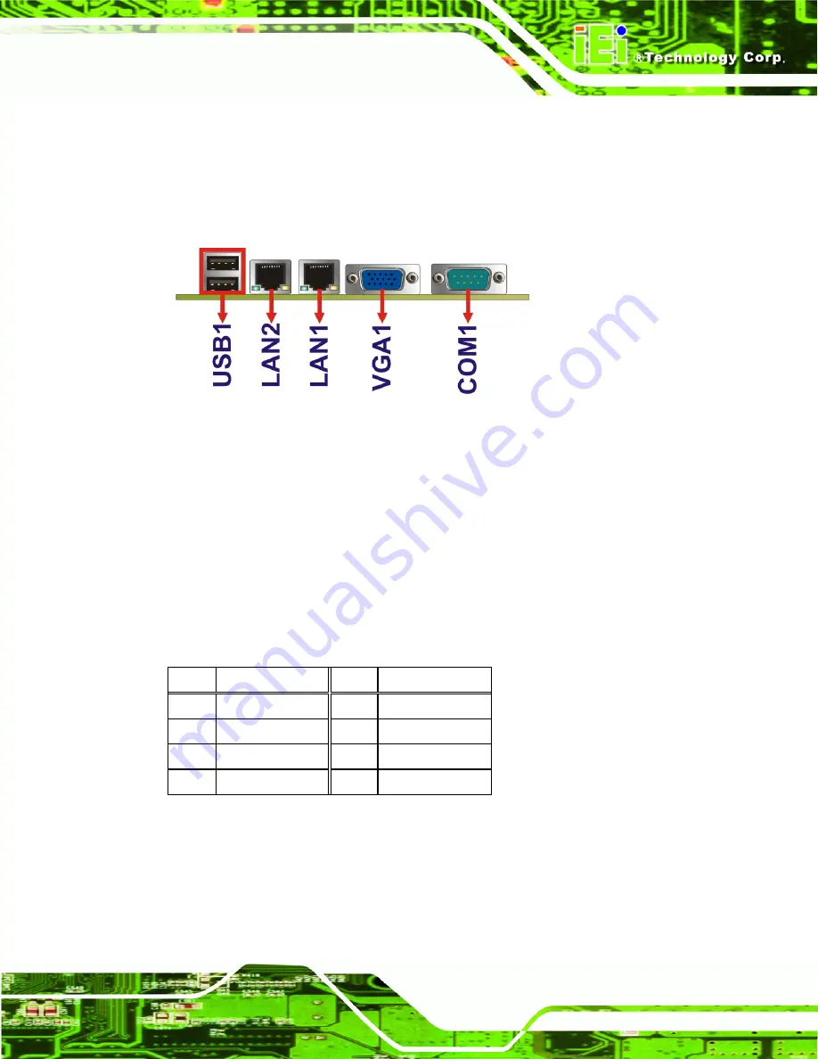
Figure 3-23 shows the WAFER-PV-D5252/D4252/N4552 motherboard external interface
connectors. The WAFER-PV-D5252/D4252/N4552 on-board external interface
connectors are shown in Figure 3-23
.
Figure 3-23: External Interface Connectors
3.3.1 Ethernet Connectors
CN Label:
LAN1, LAN2
CN Type:
RJ-45
CN Location:
CN Pinouts:
A 10/100/1000 Mb/s connection can be made to a Local Area Network.
Pin Description
Pin Description
1 MDIA3-
5 MDIA1+
2 MDIA3+
6 MDIA2+-
3.
MDIA2-
7
MDIA0-
4.
MDIA1-
8
MDIA0+
Table 3-23: Ethernet Connector Pinouts
Summary of Contents for WAFER-PV-D4252
Page 14: ...WAFER PV D5252 D4252 N4552 SBC Page 1 Chapter 1 1 Introduction...
Page 18: ...WAFER PV D5252 D4252 N4552 SBC Page 5 Figure 1 4 Dimensions with Heatsink mm...
Page 22: ...WAFER PV D5252 D4252 N4552 SBC Page 9 Chapter 2 2 Packing List...
Page 26: ...WAFER PV D5252 D4252 N4552 SBC Page 13 Chapter 3 3 Connector Pinouts...
Page 52: ...WAFER PV D5252 D4252 N4552 SBC Page 39 Chapter 4 4 Installation...
Page 76: ...WAFER PV D5252 D4252 N4552 SBC Page 63 Chapter 5 5 BIOS...
Page 104: ...WAFER PV D5252 D4252 N4552 SBC Page 91 Appendix A A BIOS Options...
Page 107: ...WAFER PV D5252 D4252 N4552 SBC Page 94 Appendix B B One Key Recovery...
Page 135: ...WAFER PV D5252 D4252 N4552 SBC Page 122 Appendix C C Terminology...
Page 139: ...WAFER PV D5252 D4252 N4552 SBC Page 126 Appendix D D Hazardous Materials Disclosure...

