WAFER-ULT/ULT2-i1 3.5" SBC
Page 92
Î
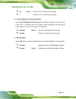
Parity [None]
Use the
Parity
option to specify the parity bit that can be sent with the data bits for
detecting the transmission errors.
Î
None D
EFAULT
No parity bit is sent with the data bits.
Î
Even
The parity bit is 0 if the number of ones in the data
bits is even.
Î
Odd
The parity bit is 0 if the number of ones in the data
bits is odd.
Î
Mark
The parity bit is always 1. This option does not
provide error detection.
Î
Space
The parity bit is always 0. This option does not
provide error detection.
Î
Stop Bits [1]
Use the
Stop Bits
option to specify the number of stop bits used to indicate the end of a
serial data packet. Communication with slow devices may require more than 1 stop bit.
Î
1 D
EFAULT
Sets the number of stop bits at 1.
Î
2
Sets the number of stop bits at 2.
Summary of Contents for WAFER-ULT-i1
Page 9: ...WAFER ULT ULT2 i1 3 5 SBC Page ix E WATCHDOG TIMER 144 F HAZARDOUS MATERIALS DISCLOSURE 147...
Page 16: ...WAFER ULT ULT2 i1 3 5 SBC Page 1 Chapter 1 1 Introduction...
Page 21: ...WAFER ULT ULT2 i1 3 5 SBC Page 6 Figure 1 3 WAFER ULT ULT2 i1 Dimensions mm...
Page 26: ...WAFER ULT ULT2 i1 3 5 SBC Page 11 Chapter 2 2 Packing List...
Page 31: ...WAFER ULT ULT2 i1 3 5 SBC Page 16 Chapter 3 3 Connectors...
Page 64: ...WAFER ULT ULT2 i1 3 5 SBC Page 49 Chapter 4 4 Installation...
Page 88: ...WAFER ULT ULT2 i1 3 5 SBC Page 73 Chapter 5 5 BIOS...
Page 127: ...WAFER ULT ULT2 i1 3 5 SBC Page 112 6 Software Drivers Chapter 6...
Page 147: ...WAFER ULT ULT2 i1 3 5 SBC Page 132 Appendix A A Regulatory Compliance...
Page 149: ...WAFER ULT ULT2 i1 3 5 SBC Page 134 Appendix B B BIOS Options...
Page 152: ...WAFER ULT ULT2 i1 3 5 SBC Page 137 Appendix C C Terminology...
Page 156: ...WAFER ULT ULT2 i1 3 5 SBC Page 141 Appendix D D Digital I O Interface...
Page 159: ...WAFER ULT ULT2 i1 3 5 SBC Page 144 Appendix E E Watchdog Timer...
Page 162: ...WAFER ULT ULT2 i1 3 5 SBC Page 147 Appendix F F Hazardous Materials Disclosure...


