WAFER-ULT5 SBC
Page 25
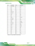
Pin
Description
Pin
Description
31
NC
32
NC
33
GND
34
NC
35
P
36
GND
37
PCIE_TX0-
38
NC
39
GND
40
NC
41
P
42
NC
43
PCIE_RX0-
44
NC
45
GND
46
NC
47
CL
48
NC
49
CLK_PCIE0-
50
NC
51
GND
52
BUF_PLT_RST#
53
PCIE_CLKREQ#
54
Pull Up +V3.3A
55
PCIE_WAKE#
56
Pull Up +V3.3A
57
GND
58
NC
59
P
60
NC
61
PCIE_TX1-
62
NC
63
GND
64
NC
65
P
66
NC
67
PCIE_RX1-
68
NC
69
GND
70
NC
71
CL
72
+V3.3A
73
CLK_PCIE1-
74
+V3.3A
75
GND
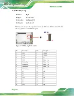
Table 3-11: M.2 A-Key Slot Pinouts
Summary of Contents for WAFER-ULT5
Page 13: ...WAFER ULT5 SBC Page 1 Chapter 1 1 Introduction...
Page 21: ...WAFER ULT5 SBC Page 9 Chapter 2 2 Unpacking...
Page 25: ...WAFER ULT5 SBC Page 13 Chapter 3 3 Connectors...
Page 54: ...WAFER ULT5 SBC Page 42 Chapter 4 4 Installation...
Page 71: ...WAFER ULT5 SBC Page 59 Chapter 5 5 BIOS...
Page 109: ...WAFER ULT5 SBC Page 97 Chapter 6 6 Software Drivers...
Page 112: ...WAFER ULT5 SBC Page 100 Appendix A A Regulatory Compliance...
Page 114: ...WAFER ULT5 SBC Page 102 B Product Disposal Appendix B...
Page 116: ...WAFER ULT5 SBC Page 104 Appendix C C BIOS Menu Options...
Page 119: ...WAFER ULT5 SBC Page 107 Appendix D D Digital I O Interface...
Page 122: ...WAFER ULT5 SBC Page 110 Appendix E E Watchdog Timer...
Page 125: ...WAFER ULT5 SBC Page 113 Appendix F F Error Beep Code...
Page 127: ...WAFER ULT5 SBC Page 115 Appendix G G Hazardous Materials Disclosure...

