WAFER-ULT5 SBC
Page 52
4.7 Chassis Installation
4.7.1 Heat Spreader
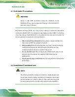
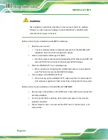
WARNING:
The heat spreader installed on the WAFER-ULT5 can only serve as a heat
conductor, which needs additional heat dissipation mechanism to achieve
suitable thermal condition. DO NOT put the WAFER-ULT5 with the heat
spreader directly on a surface that cannot dissipate system heat, and never run
the WAFER-ULT5 without the heat spreader secured to the board.
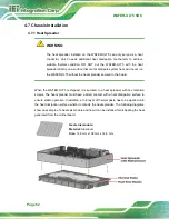
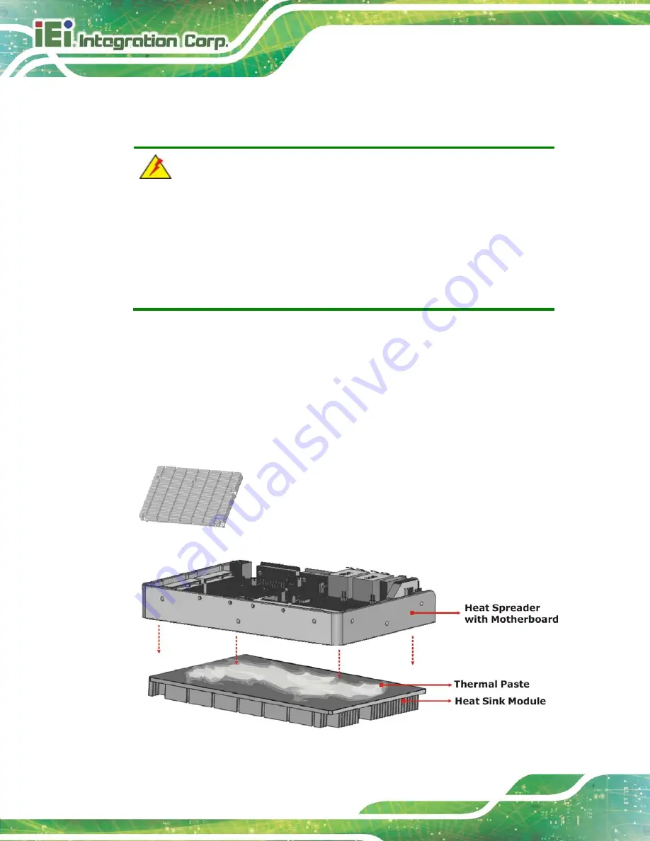
When the WAFER-ULT5 is shipped, it is secured to a heat spreader with five retention
screws. The heat spreader must have a direct contact with a heat dissipation surface to
ensure stable operation. In addition, a thin layer of thermal paste has to be applied onto
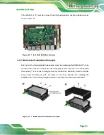
the heat dissipation surface where it contacts the heat spreader. The following diagrams
show an example of a heat sink module and how it can be installed for dissipating the heat
generated from the motherboard:
Heat sink module:
Material:
Aluminum
Size:
146 mm x 102 mm x 14.6 mm
Summary of Contents for WAFER-ULT5
Page 13: ...WAFER ULT5 SBC Page 1 Chapter 1 1 Introduction...
Page 21: ...WAFER ULT5 SBC Page 9 Chapter 2 2 Unpacking...
Page 25: ...WAFER ULT5 SBC Page 13 Chapter 3 3 Connectors...
Page 54: ...WAFER ULT5 SBC Page 42 Chapter 4 4 Installation...
Page 71: ...WAFER ULT5 SBC Page 59 Chapter 5 5 BIOS...
Page 109: ...WAFER ULT5 SBC Page 97 Chapter 6 6 Software Drivers...
Page 112: ...WAFER ULT5 SBC Page 100 Appendix A A Regulatory Compliance...
Page 114: ...WAFER ULT5 SBC Page 102 B Product Disposal Appendix B...
Page 116: ...WAFER ULT5 SBC Page 104 Appendix C C BIOS Menu Options...
Page 119: ...WAFER ULT5 SBC Page 107 Appendix D D Digital I O Interface...
Page 122: ...WAFER ULT5 SBC Page 110 Appendix E E Watchdog Timer...
Page 125: ...WAFER ULT5 SBC Page 113 Appendix F F Error Beep Code...
Page 127: ...WAFER ULT5 SBC Page 115 Appendix G G Hazardous Materials Disclosure...

