WAFER-ULT5 SBC
Page 20
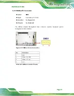
3.2.5 Front Panel Connector
CN Label:
F_PANEL1
CN Type:
6-pin wafer, p=2.00 mm
CN Location:
See
CN Pinouts:
See
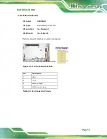
The front panel connector connects to the power LED indicator and HDD LED indicator on
the system front panel.
Figure 3-6: Front Panel Connector Location
Pin
Description
1
VCC
2
GND
3
4
PWR_LED-
5
6
HDD_LED-
Table 3-7: Front Panel Connector Pinouts
Summary of Contents for WAFER-ULT5
Page 13: ...WAFER ULT5 SBC Page 1 Chapter 1 1 Introduction...
Page 21: ...WAFER ULT5 SBC Page 9 Chapter 2 2 Unpacking...
Page 25: ...WAFER ULT5 SBC Page 13 Chapter 3 3 Connectors...
Page 54: ...WAFER ULT5 SBC Page 42 Chapter 4 4 Installation...
Page 71: ...WAFER ULT5 SBC Page 59 Chapter 5 5 BIOS...
Page 109: ...WAFER ULT5 SBC Page 97 Chapter 6 6 Software Drivers...
Page 112: ...WAFER ULT5 SBC Page 100 Appendix A A Regulatory Compliance...
Page 114: ...WAFER ULT5 SBC Page 102 B Product Disposal Appendix B...
Page 116: ...WAFER ULT5 SBC Page 104 Appendix C C BIOS Menu Options...
Page 119: ...WAFER ULT5 SBC Page 107 Appendix D D Digital I O Interface...
Page 122: ...WAFER ULT5 SBC Page 110 Appendix E E Watchdog Timer...
Page 125: ...WAFER ULT5 SBC Page 113 Appendix F F Error Beep Code...
Page 127: ...WAFER ULT5 SBC Page 115 Appendix G G Hazardous Materials Disclosure...

