WAFER-ULT5 SBC
Page 32
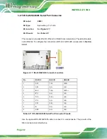
3.2.16 RS-232/422/485 Serial Port Connector
CN Label:
COM1
CN Type:
9-pin wafer, p=1.25 mm
CN Location:
See
CN Pinouts:
See
This connector provides RS-232, RS-422 or RS-485 communications. The default mode is
set to RS-232. To configure the connectors as RS-422 or RS-485, please refer to
Section
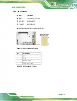
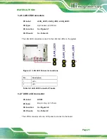
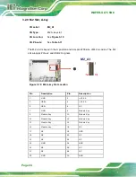
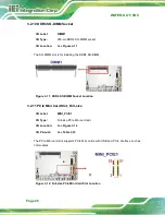
Figure 3-17: RS-232/422/485 Connector Location
Pin
RS-232
RS-422
RS-485
1
DCD
TXD-
DATA-
2
DSR
N/A
N/A
3
RXD
TXD+
DATA+
4
RTS
N/A
N/A
5
TXD
RXD+
N/A
6
CTS
N/A
N/A
7
DTR
RXD-
N/A
8
RI
N/A
N/A
9
GND
N/A
N/A
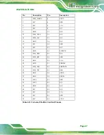
Table 3-17: RS-232/422/485 Serial Port Connector Pinouts
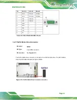
Use the optional RS-232/422/485 cable to connect to a serial device. The pinouts of the
DB-9 connector are listed below.
Summary of Contents for WAFER-ULT5
Page 13: ...WAFER ULT5 SBC Page 1 Chapter 1 1 Introduction...
Page 21: ...WAFER ULT5 SBC Page 9 Chapter 2 2 Unpacking...
Page 25: ...WAFER ULT5 SBC Page 13 Chapter 3 3 Connectors...
Page 54: ...WAFER ULT5 SBC Page 42 Chapter 4 4 Installation...
Page 71: ...WAFER ULT5 SBC Page 59 Chapter 5 5 BIOS...
Page 109: ...WAFER ULT5 SBC Page 97 Chapter 6 6 Software Drivers...
Page 112: ...WAFER ULT5 SBC Page 100 Appendix A A Regulatory Compliance...
Page 114: ...WAFER ULT5 SBC Page 102 B Product Disposal Appendix B...
Page 116: ...WAFER ULT5 SBC Page 104 Appendix C C BIOS Menu Options...
Page 119: ...WAFER ULT5 SBC Page 107 Appendix D D Digital I O Interface...
Page 122: ...WAFER ULT5 SBC Page 110 Appendix E E Watchdog Timer...
Page 125: ...WAFER ULT5 SBC Page 113 Appendix F F Error Beep Code...
Page 127: ...WAFER ULT5 SBC Page 115 Appendix G G Hazardous Materials Disclosure...


