WAFER-ULT5 SBC
Page 53
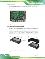
If the WAFER-ULT5 must be removed from the heat spreader, the five retention screws
must be removed.
Figure 4-11: Heat Sink Retention Screws
4.7.2 Motherboard Installation Example
Each side of the heat spreader has several screw holes allowing the WAFER-ULT5 to be
mounted into a chassis or a heat sink enclosure (please refer to Figure 1-3 for the detailed
dimensions). The user has to design or select a chassis or a heat sink enclosure that has
screw holes matching up with the holes on the heat spreader for installing the
WAFER-ULT5. The following diagram shows an example of motherboard installation.
Figure 4-12: Motherboard Installation Example
Summary of Contents for WAFER-ULT5
Page 13: ...WAFER ULT5 SBC Page 1 Chapter 1 1 Introduction...
Page 21: ...WAFER ULT5 SBC Page 9 Chapter 2 2 Unpacking...
Page 25: ...WAFER ULT5 SBC Page 13 Chapter 3 3 Connectors...
Page 54: ...WAFER ULT5 SBC Page 42 Chapter 4 4 Installation...
Page 71: ...WAFER ULT5 SBC Page 59 Chapter 5 5 BIOS...
Page 109: ...WAFER ULT5 SBC Page 97 Chapter 6 6 Software Drivers...
Page 112: ...WAFER ULT5 SBC Page 100 Appendix A A Regulatory Compliance...
Page 114: ...WAFER ULT5 SBC Page 102 B Product Disposal Appendix B...
Page 116: ...WAFER ULT5 SBC Page 104 Appendix C C BIOS Menu Options...
Page 119: ...WAFER ULT5 SBC Page 107 Appendix D D Digital I O Interface...
Page 122: ...WAFER ULT5 SBC Page 110 Appendix E E Watchdog Timer...
Page 125: ...WAFER ULT5 SBC Page 113 Appendix F F Error Beep Code...
Page 127: ...WAFER ULT5 SBC Page 115 Appendix G G Hazardous Materials Disclosure...


