WAFER-ULT5 SBC
Page 55
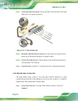
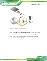
Step 3:
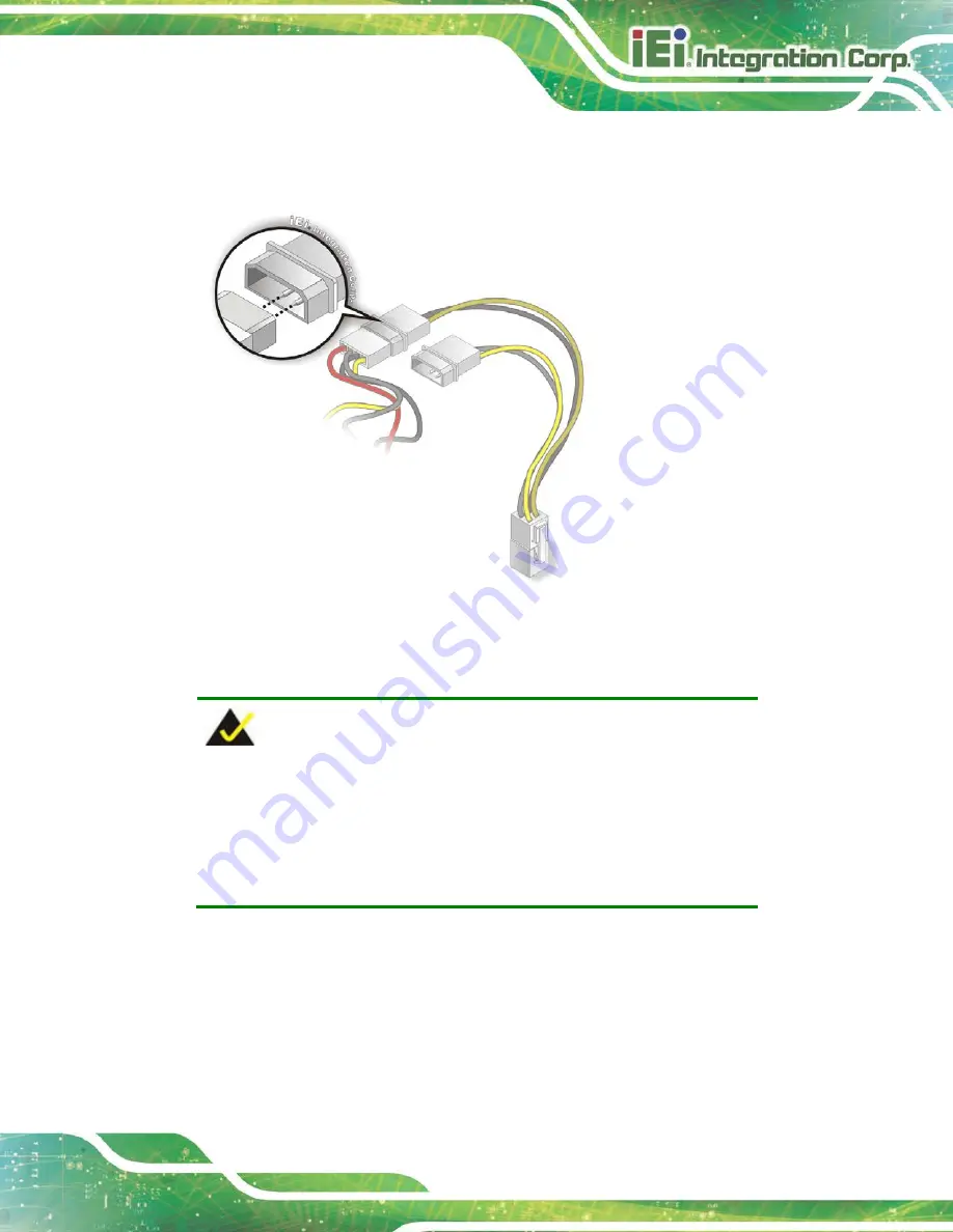
Connect power cable to power supply
. Connect one of the 4-pin (1x4) Molex
type power cable connectors to an AT power supply. See Figure 4-14.
Figure 4-14: Connect Power Cable to Power Supply
4.8.2 7.1 Channel Audio Kit Installation
NOTE:
This item must be ordered separately, and connects to the audio
connector. For further information please contact the nearest
distributor, reseller or vendor or contact an IEI sales representative
directly.
The audio kit attaches to the audio connector. The audio kit provides 7.1 channel audio.
To install the audio kit, please refer to the steps below:
Step 1:
Connect the cable to the audio kit.
Connect the included cable to the audio kit.
Make sure pin 1 aligns with the marked pin.
Summary of Contents for WAFER-ULT5
Page 13: ...WAFER ULT5 SBC Page 1 Chapter 1 1 Introduction...
Page 21: ...WAFER ULT5 SBC Page 9 Chapter 2 2 Unpacking...
Page 25: ...WAFER ULT5 SBC Page 13 Chapter 3 3 Connectors...
Page 54: ...WAFER ULT5 SBC Page 42 Chapter 4 4 Installation...
Page 71: ...WAFER ULT5 SBC Page 59 Chapter 5 5 BIOS...
Page 109: ...WAFER ULT5 SBC Page 97 Chapter 6 6 Software Drivers...
Page 112: ...WAFER ULT5 SBC Page 100 Appendix A A Regulatory Compliance...
Page 114: ...WAFER ULT5 SBC Page 102 B Product Disposal Appendix B...
Page 116: ...WAFER ULT5 SBC Page 104 Appendix C C BIOS Menu Options...
Page 119: ...WAFER ULT5 SBC Page 107 Appendix D D Digital I O Interface...
Page 122: ...WAFER ULT5 SBC Page 110 Appendix E E Watchdog Timer...
Page 125: ...WAFER ULT5 SBC Page 113 Appendix F F Error Beep Code...
Page 127: ...WAFER ULT5 SBC Page 115 Appendix G G Hazardous Materials Disclosure...

