WAFER-ULT5 SBC
Page 56
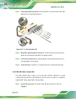
Step 2:
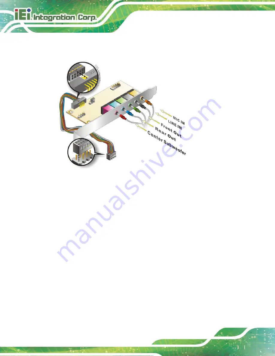
Conect the cable to the board
. Connect the other end of the cable to the board.
Make sure to line up the marked pin 1.
Figure 4-15: 7.1 Channel Audio Kit
Step 3:
Mount the audio kit onto the chassis
. Once the audio kit is connected to the
board, secure the audio kit bracket to the system chassis.
Step 4:
Connect the audio devices
. Connect speakers and external audio sources to
the audio jacks on the audio kit.
Step 5:
Install the driver
. Install the 7.1 channel audio driver included with the board.
Step 0:
4.8.3 RS-232 Cable Connection
The single RS-232 cable consists of one serial port connector attached to a serial
communications cable that is then attached to a D-sub 9 male connector. To install the
single RS-232 cable, please follow the steps below.
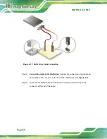
Step 1:
Locate the connector
. The location of the RS-232 connector is shown in
Chapter 3
.
Summary of Contents for WAFER-ULT5
Page 13: ...WAFER ULT5 SBC Page 1 Chapter 1 1 Introduction...
Page 21: ...WAFER ULT5 SBC Page 9 Chapter 2 2 Unpacking...
Page 25: ...WAFER ULT5 SBC Page 13 Chapter 3 3 Connectors...
Page 54: ...WAFER ULT5 SBC Page 42 Chapter 4 4 Installation...
Page 71: ...WAFER ULT5 SBC Page 59 Chapter 5 5 BIOS...
Page 109: ...WAFER ULT5 SBC Page 97 Chapter 6 6 Software Drivers...
Page 112: ...WAFER ULT5 SBC Page 100 Appendix A A Regulatory Compliance...
Page 114: ...WAFER ULT5 SBC Page 102 B Product Disposal Appendix B...
Page 116: ...WAFER ULT5 SBC Page 104 Appendix C C BIOS Menu Options...
Page 119: ...WAFER ULT5 SBC Page 107 Appendix D D Digital I O Interface...
Page 122: ...WAFER ULT5 SBC Page 110 Appendix E E Watchdog Timer...
Page 125: ...WAFER ULT5 SBC Page 113 Appendix F F Error Beep Code...
Page 127: ...WAFER ULT5 SBC Page 115 Appendix G G Hazardous Materials Disclosure...


