TECHNICAL SPECIFICATIONS
2
30
2.
0
2
8
- 10 -
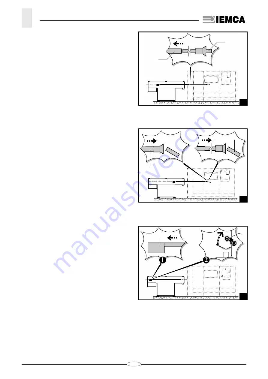
– After each feeding, the bar pusher
E
moves back
from the bar
– The bar remnant
F
is ejected either directly by the
bar pusher
E
or by the next bar
G
which is fed
– The bar pusher
E
strokes back and rises (fig. 11).
– The feeder begins a new automatic working cycle.
28_010_1
•
•
E
B
28_011_1
•
•
E
F
G
F
•
•
28_012_1
•
E
E
Summary of Contents for VIP 80
Page 1: ...REL DATA COD S N VIP 80 MANUAL FOR USE AND MAINTENANCE GB 1 03 11 99 805005440 ...
Page 28: ...HANDLING AND INSTALLATION 4 25 302 028 ...
Page 61: ...PUSH BUTTON PANEL OPERATION GUIDE GB 03 11 99 VIP 80 AUTOMATIC BAR FEEDER ...
Page 64: ...2 302 061 ...
Page 74: ...12 1 GENERAL INFORMATION 302 061 ...
Page 136: ......
Page 138: ......
Page 142: ...302 061 B ...
Page 144: ......
Page 148: ......
Page 150: ......
Page 152: ......


