HANDLING AND INSTALLATION
4
30
2.
0
2
8
- 21 -
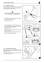
4.5.2
Height - Adjustment
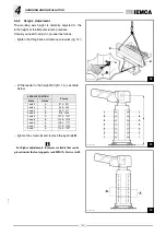
The working axis height is normally adjusted to the
lathe height at the Manufacturer's premises.
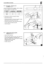
Should you need to adjust it, proceed as follows:
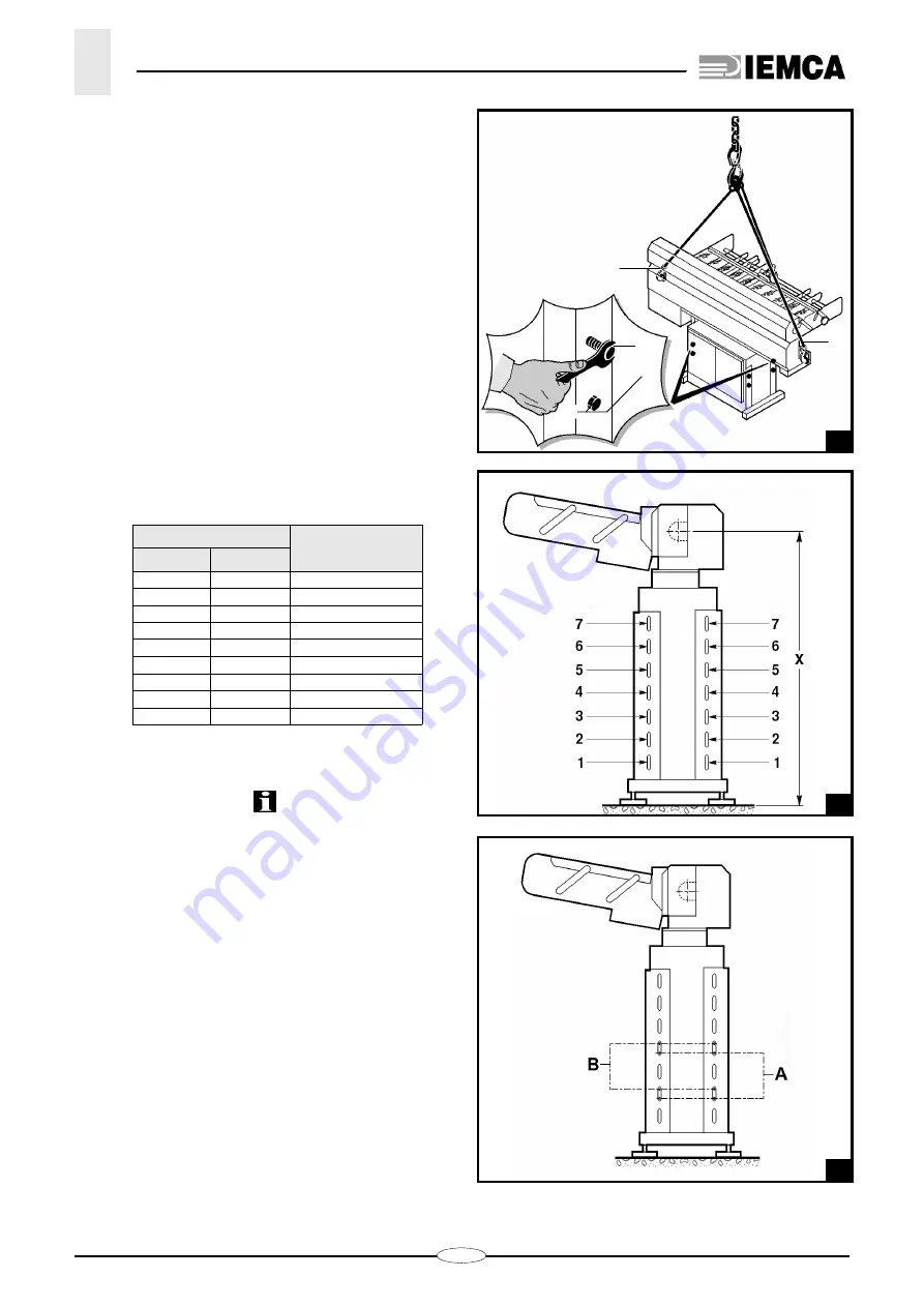
– tighten the lifting belts and remove screws
;
– lift the feeder to the height
X
(fig13 -14); see table
below:
– tighten the screws
A
and remove the eyebolts
B
.
For higher adjustments, shims are available that can be
placed under the foot supports (ask IEMCA Service staff).
SCREWS POSITION
X (mm)
Slots
Holes
1 and 3
A
870 - 907
2 and 4
B
908 - 939
2 and 4
A
940 - 977
3 and 5
B
978 - 1009
3 and 5
A
1010 - 1047
4 and 6
B
1048 - 1079
4 and 6
A
1080 - 1117
5 and 7
B
1118 - 1149
5 and 7
A
1150 - 1187
28_027_1.bmp
B
A
A
B
28_028_1.bmp
14
28_083_0.bmp
Summary of Contents for VIP 80
Page 1: ...REL DATA COD S N VIP 80 MANUAL FOR USE AND MAINTENANCE GB 1 03 11 99 805005440 ...
Page 28: ...HANDLING AND INSTALLATION 4 25 302 028 ...
Page 61: ...PUSH BUTTON PANEL OPERATION GUIDE GB 03 11 99 VIP 80 AUTOMATIC BAR FEEDER ...
Page 64: ...2 302 061 ...
Page 74: ...12 1 GENERAL INFORMATION 302 061 ...
Page 136: ......
Page 138: ......
Page 142: ...302 061 B ...
Page 144: ......
Page 148: ......
Page 150: ......
Page 152: ......


