ADJUSTMENTS AND SETUP
5
30
2.
0
2
8
- 30 -
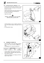
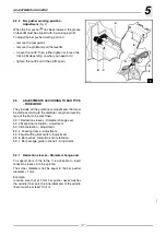
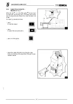
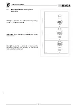
5.3.5
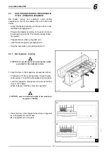
Guide lifting limit switch -
Adjustment.
When the bar
A
, is on the lifted guide
B
, its axis must
coincide with the loading axis. The lifting limit switch
must be adjusted according to the stock diameter and
shape.
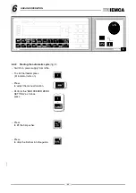
To adjust it, proceed as follows:
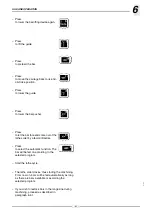
– press
to start the feeder;
– press
to select the manual function;
– press to lift the guide;
– adjust the guide lifting limit stop through screw
C
(fig. 8) and check the adjustment through the gra-
duated scale
D
.
28_047_1.bmp
A
B
A
28.048 Ec.1
B
C
D
Summary of Contents for VIP 80
Page 1: ...REL DATA COD S N VIP 80 MANUAL FOR USE AND MAINTENANCE GB 1 03 11 99 805005440 ...
Page 28: ...HANDLING AND INSTALLATION 4 25 302 028 ...
Page 61: ...PUSH BUTTON PANEL OPERATION GUIDE GB 03 11 99 VIP 80 AUTOMATIC BAR FEEDER ...
Page 64: ...2 302 061 ...
Page 74: ...12 1 GENERAL INFORMATION 302 061 ...
Page 136: ......
Page 138: ......
Page 142: ...302 061 B ...
Page 144: ......
Page 148: ......
Page 150: ......
Page 152: ......

