
ADJUSTMENTS AND SETUP
5
- 31 -
3
02.
0
2
8
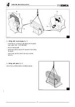
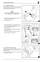
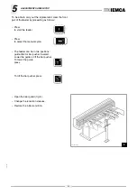
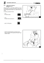
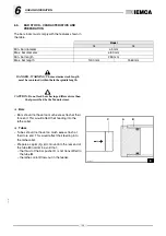
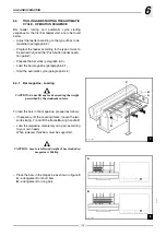
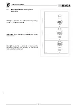
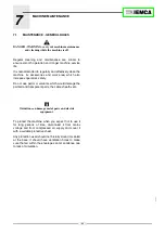
5.3.6
Bar pusher - Selection and
installation
Install a bar pusher with a diameter which is suitable
for the bar diameter (see table below).
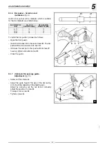
To install the bar pusher, proceed as follows:
– Open the front guard.
– Install the fore bush
C
in the seat of lever
D
. The bar
pusher
E
must be inserted into bush
C
.
– Introduce the rear part of bar pusher
E
into lever
F
housing, tighten screw
G
and nut
H
.
– Close the guard.
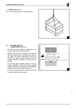
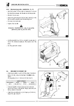
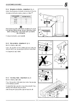
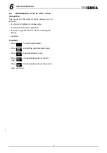
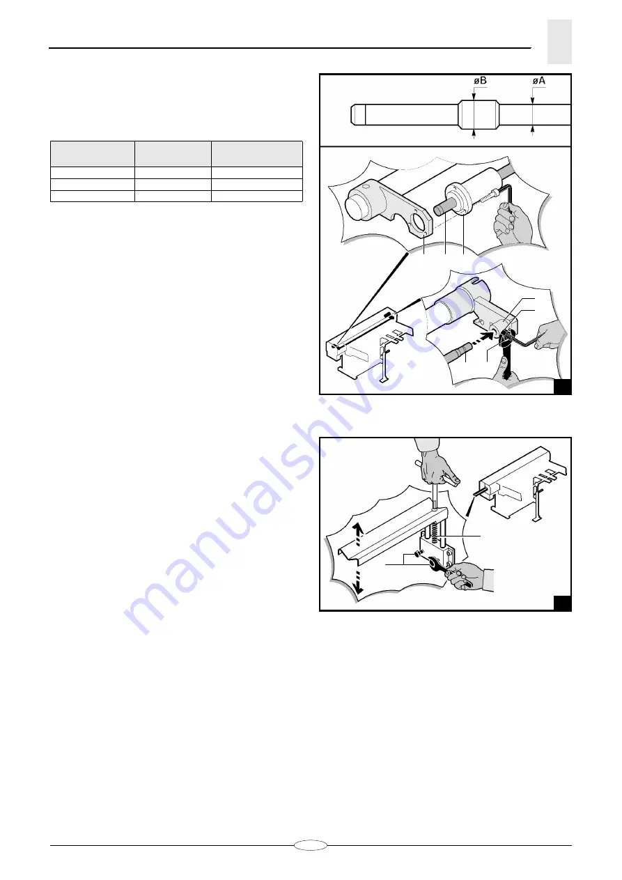
5.3.7
(Optional) Bar passage guide -
Adjustment
– Screw out the screws
A
.
– Adjust the guide height. The axis of the bar resting
on it should be aligned with the feeding axis.
Adjust by screwing out the nut
A
and manually
adjust the position of screw
B
.
To adjust, turn screw
B
.
– Tighten screws
A
.
BAR DIAMETER
(mm)
ØA - ROD
DIAMETER (MM)
ØB - BEARING
DIAMETER (MM)
5
÷
12
10
12
10
÷
19
12
15
16
÷
80
18
21
28.049 Ec.2
E
D
C
E
F
H
G
28.050 Ec.1
A
B
Summary of Contents for VIP 80
Page 1: ...REL DATA COD S N VIP 80 MANUAL FOR USE AND MAINTENANCE GB 1 03 11 99 805005440 ...
Page 28: ...HANDLING AND INSTALLATION 4 25 302 028 ...
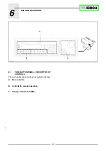
Page 61: ...PUSH BUTTON PANEL OPERATION GUIDE GB 03 11 99 VIP 80 AUTOMATIC BAR FEEDER ...
Page 64: ...2 302 061 ...
Page 74: ...12 1 GENERAL INFORMATION 302 061 ...
Page 136: ......
Page 138: ......
Page 142: ...302 061 B ...
Page 144: ......
Page 148: ......
Page 150: ......
Page 152: ......


