18
2
INSTALLATION PROCEDURE
302.061
2.1.1 Operator parameters - Description
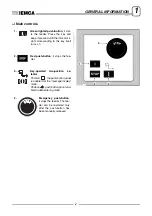
Defines the position of the point at which the bar feeder must
send the "END OF BAR" signal to the lathe.
It is a value referred to point
F
(maximum bar pusher feed
point), and corresponds to the length of the workpiece plus the
thickness of the cutting tool.
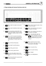
Defines the movement of the bar head with reference
to point
C
(facing point).
Both positive and negative values can be entered.
Defines the facing.
1 -
“
In position
”; the bar is positioned at the point defined in
parameter 2
.
0 -
“
To the stop
”; the bar moves past the point defined in
parameter 2
until
it meets the bar stop or the tool.
1
Phase
machining
: >
1 0 0 ( mm )
( i n c h e s )
n o . 1
B a r
e n d
a d j u s t m e n t
IDM - 61.006 Ec.0
Parameter 1
2
Phase
bar change
: >
0 ( mm )
0 ( i n c h e s )
n o . 2
F a c i n g
l e n g t h
C
IDM - 61.007 Ec.0
Parameter 2
(positive value)
Parameter 2
(negative value)
3
Phase
bar change
: > 0
n o . 3
F a c i n g
m o d e
Summary of Contents for VIP 80
Page 1: ...REL DATA COD S N VIP 80 MANUAL FOR USE AND MAINTENANCE GB 1 03 11 99 805005440 ...
Page 28: ...HANDLING AND INSTALLATION 4 25 302 028 ...
Page 61: ...PUSH BUTTON PANEL OPERATION GUIDE GB 03 11 99 VIP 80 AUTOMATIC BAR FEEDER ...
Page 64: ...2 302 061 ...
Page 74: ...12 1 GENERAL INFORMATION 302 061 ...
Page 136: ......
Page 138: ......
Page 142: ...302 061 B ...
Page 144: ......
Page 148: ......
Page 150: ......
Page 152: ......


