19
2
INSTALLATION PROCEDURE
302.061
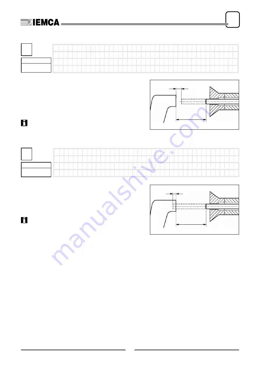
With each feed, it checks that the bar feeding corresponds to
the value set at
parameter 6
while remaining within the tole-
rance set at
parameter 4
. If for any reason this does not hap-
pen, when the lathe disables the “FEEDING” signal the bar
feeder goes into “ALARM”.
Set the tolerance.
INFORMATION: this control is not active for the first pie-
ce during the bar change phase, nor for the first piece when
switching from manual cycle to automatic cycle.
With each feed, it checks that the bar feeding does not exceed
the value set at
parameter 6
, added to the value set at
para-
meter 5
. If for any reason this does not happen, the bar feeder
goes into “ALARM”.
Set the tolerance.
INFORMATION: On sliding headstock lathes, this parame-
ter can be used to check for tool damage. Set this value to a few
millimetres (max. 5 mm).
: >
0 ( mm )
0 ( i n c h e s )
n o . 4
S h o r t
f e e d
s a f e t y
4
Phase
machining
IDM - 61.024 Ec.0
parameter 4
parameter 6
5
Phase
machining
: >
0 ( mm )
0 ( i n c h e s )
n o . 5
L o n g
f e e d
s a f e t y
IDM - 61.025 Ec.0
parameter 5
parameter 6
Summary of Contents for VIP 80
Page 1: ...REL DATA COD S N VIP 80 MANUAL FOR USE AND MAINTENANCE GB 1 03 11 99 805005440 ...
Page 28: ...HANDLING AND INSTALLATION 4 25 302 028 ...
Page 61: ...PUSH BUTTON PANEL OPERATION GUIDE GB 03 11 99 VIP 80 AUTOMATIC BAR FEEDER ...
Page 64: ...2 302 061 ...
Page 74: ...12 1 GENERAL INFORMATION 302 061 ...
Page 136: ......
Page 138: ......
Page 142: ...302 061 B ...
Page 144: ......
Page 148: ......
Page 150: ......
Page 152: ......


