


24
2
INSTALLATION PROCEDURE
302.061
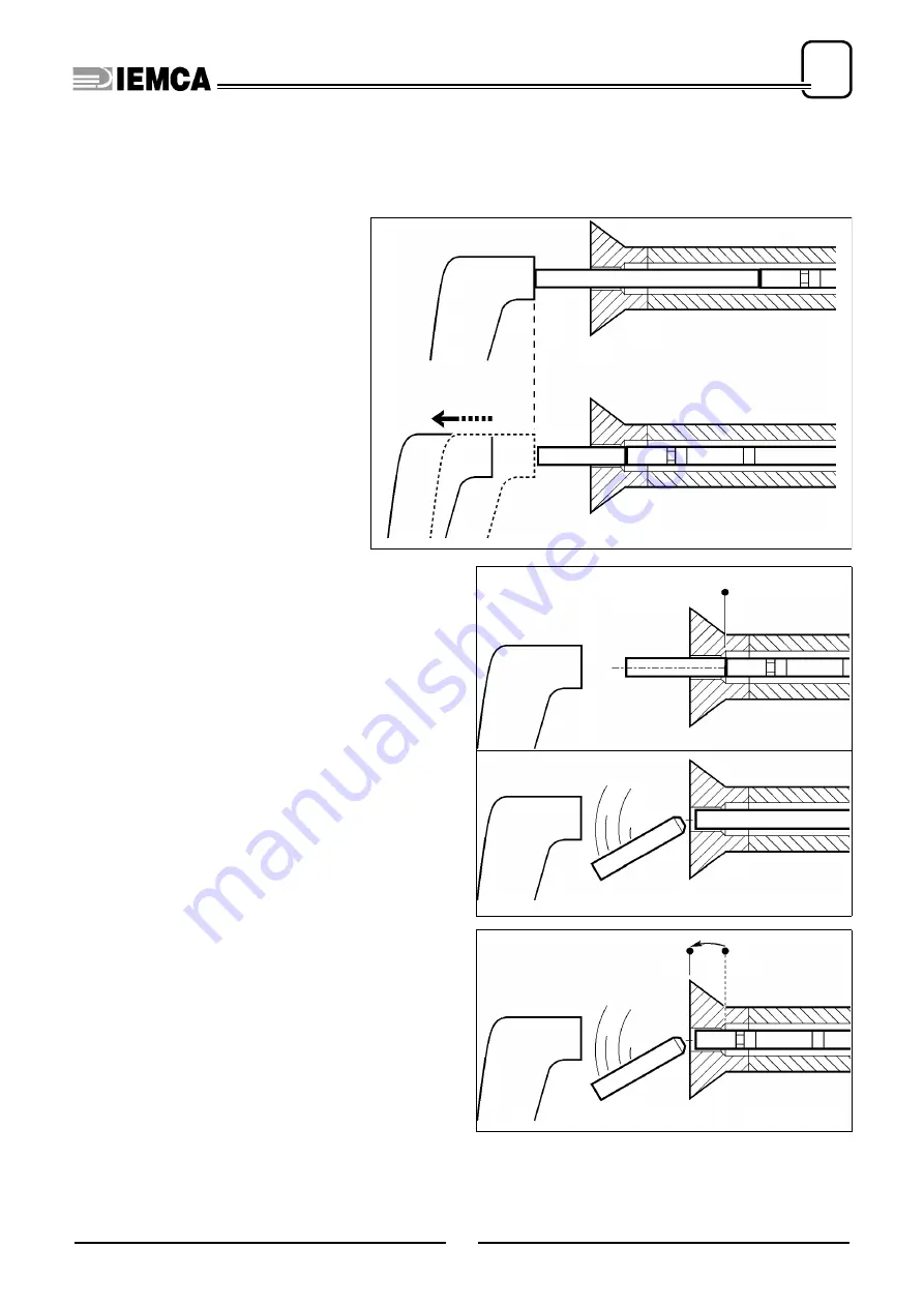
Mode 1 - “Ejection” or 2 - “Bar change advance”
Introduction
These modes can be implemented
only if the lathe allows subprograms.
The subprogram must move away the
stop after the “bar end” signal.
When the stop is moved away, the bar
remnant can be ejected from the lathe
side.
1 - “Ejection”
Either of two options are possible:
a)
Ejection with the new bar.
b)
Ejection with the bar pusher.
a)
Ejection with the new bar.
Stage sequence:
Phase 1
- The lathe receives the “END OF BAR” si-
gnal from the bar feeder, it completes the
last workpiece, then enters the subpro-
gram (bar stop removal) and displays the
“FEEDING” and “BAR CHANGE” signals;
Phase 2a
- The bar pusher moves forward until point
F
(max. bar pusher feed point) and the bar
feeder carries out the bar change;
Phase 3a
- The new bar, in its forward movement,
ejects the bar remnant and moves to the
facing position.
b) Ejection with the bar pusher.
Move point
F
(max. bar pusher feed point,
parameter
29
) flush with the collet.
Stage sequence:
Phase 1
- The lathe receives the “END OF BAR” si-
gnal from the bar feeder, it completes the
last workpiece, then enters the subpro-
gram (bar stop removal) and displays the
“FEEDING” and “BAR CHANGE” si-
gnals;
Phase 2b
- The bar pusher moves forward to point
F
and ejects the bar remnant. The bar fee-
der performs the bar change.
PROGRAM
SUBPROGRAM
IDM - 61.014 Ec.0
Phase 1
F
IDM - 61.015 Ec.0
Phase 2a
Phase 3a
IDM - 61.016 Ec.0
F
F
Phase 2b
Summary of Contents for VIP 80
Page 1: ...REL DATA COD S N VIP 80 MANUAL FOR USE AND MAINTENANCE GB 1 03 11 99 805005440 ...
Page 28: ...HANDLING AND INSTALLATION 4 25 302 028 ...
Page 61: ...PUSH BUTTON PANEL OPERATION GUIDE GB 03 11 99 VIP 80 AUTOMATIC BAR FEEDER ...
Page 64: ...2 302 061 ...
Page 74: ...12 1 GENERAL INFORMATION 302 061 ...
Page 136: ......
Page 138: ......
Page 142: ...302 061 B ...
Page 144: ......
Page 148: ......
Page 150: ......
Page 152: ......


