- 52 -
30
2.
0
2
8
9
PART REPLACEMENT
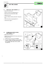
9.1.
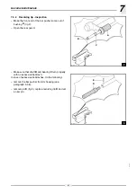
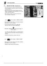
FEED CHAIN - REPLACEMENT
– Remove the front guard.
– Slacken the chain (see paragraph 5.2.1).
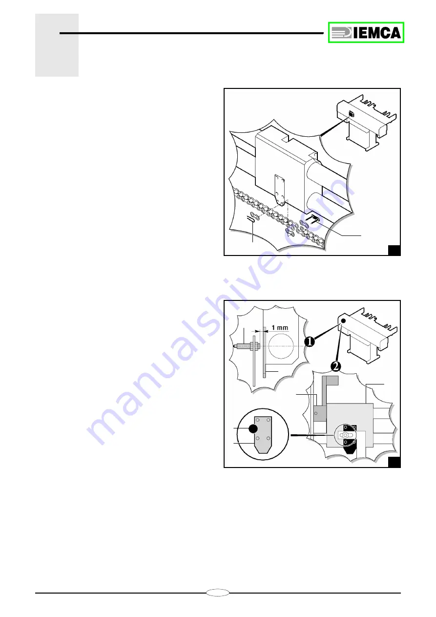
– Remove the fork pin
A
and the link
B
.
– Replace the chain.
– Fit the link
B
and the fork pin
A
back in their posi-
tion.
– Stretch the chain (see paragraph 5.2.1).
– Install the front guard.
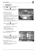
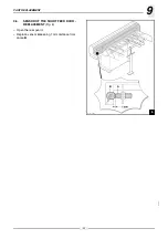
9.2.
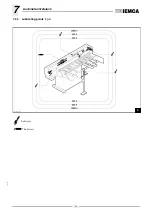
CARRIAGE BACK LIMIT SENSOR -
REPLACEMENT
– Remove the front guard.
– Replace the sensor
A
and fit the new sensor by pro-
ceeding as follows:
1 -
keep the sensor 1 mm far from plate
B
;
2 -
moving carriage
C
backwards, the sensor LED
shall turn on when the carriage abuts against lever
D
. The display shall show a -3,0 to -4,0 mm
displacement.
28.064 Ec.0
A
B
28.065 Ec.2
B
A
A
B
D
C
6
8
Summary of Contents for VIP 80
Page 1: ...REL DATA COD S N VIP 80 MANUAL FOR USE AND MAINTENANCE GB 1 03 11 99 805005440 ...
Page 28: ...HANDLING AND INSTALLATION 4 25 302 028 ...
Page 61: ...PUSH BUTTON PANEL OPERATION GUIDE GB 03 11 99 VIP 80 AUTOMATIC BAR FEEDER ...
Page 64: ...2 302 061 ...
Page 74: ...12 1 GENERAL INFORMATION 302 061 ...
Page 136: ......
Page 138: ......
Page 142: ...302 061 B ...
Page 144: ......
Page 148: ......
Page 150: ......
Page 152: ......

