background image


The information contained in this document is the property of Automatic Systems and is confidential. The recipient shall refrain from using it for any purpose other than the use of the products or the 
execution of the project to which it refers, and from communicating it to third parties without Automatic Systems’ prior written agreement. Document subject to change without notice.


BL3x-MT-EN-08  

page

 34/59


5.6. 

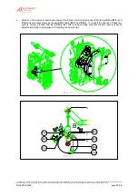
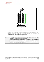
Fixing the shrouds (BL32 only) 

Fig. 13

13:2

13:1

13:3

13:4

13:5

13:8

13:6

13:7

13:6

13:7

13:9

13:10

13:11


Attention

Fixing the shrouds requires two people! 


Shrouds need to be installed for an arm boom from 7.01m (6.01m in case an option if fixed to the arm).  The 
stainless steel bracing wires (

13:1

) are factory-fixed with the collar (

13:2

) on the arm. 


When the three arm segments are fixed and secured to one another (see 

paragraphs 4.3

 and 

4.4

), proceed 

as follows: 
-- 

Unroll the cable (

13:1

) and pass it onto the upper screw of the collar (

13:2

), not forgetting to place the 

eyelet. 

-- 

Loosen the strainers (

13:3

) at maximum length. 

-- 

Remove the security pin (

13:4

) and the axle (

13:5

) from the strainers. 

-- 

Position the strainer (

13:3

) onto the wing (

13:6

) of the stretcher plates (

13:7

). 

-- 

Insert the axle (

13:5

) into the wing of the stretcher plate and fix the security pin (

13:4

) again. 

-- 

Tighten the strainers (

13:3

) so as to make the arm vertical in its open position and horizontal in its 

closed position.  If the precise positioning of the arm is not possible, see 

paragraph 4.8. 

Note

The figure above shows a two-stretcher assembly.  Proceed likewise for a single-stretcher 
assembly (lateral arm). 

Summary of Contents for Automatic Systems BL 32

Page 1: ... it for any purpose other than the use of the products or the execution of the project to which it refers and from communicating it to third parties without Automatic Systems prior written agreement Document subject to change without notice BL3x MT EN 08 Page 1 59 BL 32 BL 33 Automatic Systems Wavre OPERATING MANUAL translated from French ...

Page 2: ...oard by AS1320 version 3 6 of the program ch 4 added Addition of reinforcement stop ch 6 6 03 July 17 2007 MFy Update of the balance table ch 6 5 04 Nov 09 2007 MFy Adapt to software version 4 1 of AS1320 control board ch 4 Addition of electric diagrams for options ch 8 Update of the conformity certificates ch 10 05 Jun 18 2008 MFy Control board adapted to version 6 x of the program Revision of th...

Page 3: ...toring 16 4 2 QUICK START menu quick configuration 22 5 INSTALLATION 29 5 1 Preliminary work on site 29 5 2 Handling and installing the unit 30 5 3 Installing the lateral arm BL32 31 5 4 Installing the central arm BL32 32 5 5 Installing the oval arm BL33 33 5 6 Fixing the shrouds BL32 only 34 5 7 Dimensional views and arm segments 35 5 8 Levelling the barrier arm 37 5 9 Installing the tip support ...

Page 4: ... COULD BE SET IN MOTION THE HOOD SHOULD BE REMOVED ONLY IF YOU NEED TO REPLACE THE DRIVING SHAFT OR A SPRING ADJUST THE BELT S OR PROCEED WITH THE MAINTENANCE WARNING Never raise the arm brackets by means of the crank without the boom arm fixed for counterbalancing the spring the arm brakets would swing violently with serious injury risks for the operators IMPORTANT INFORMATION CONCERNING HEALTH S...

Page 5: ...it refers and from communicating it to third parties without Automatic Systems prior written agreement Document subject to change without notice BL3x MT EN 08 page 5 59 2 GENERAL 2 1 General view 1 1 Side door 1 2 Safety lock with keys 1 3 Arm fixing jaw 1 4 Central arm bracket BL32 1 5 Central oval arm bracket BL33 1 6 Hood 1 7 Housing 1 8 Fixing braket 1 9 Heating resistance 1 10 Emergency crank...

Page 6: ...greement Document subject to change without notice BL3x MT EN 08 page 6 59 2 2 Access to internal components Fig 2 shows the internal components of the rising barrier type BL32 BL33 as you see them when you remove the side door Fig 3 on next page shows most elements that will be referred to in this manual Please consult it whenever needed 2 1 Motor 2 2 Torque limiter 2 3 Control board 2 4 Abutment...

Page 7: ... without Automatic Systems prior written agreement Document subject to change without notice BL3x MT EN 08 page 7 59 Fig 3 3 1 3 5 3 15 3 6 3 14 3 13 3 16 3 8 3 4 3 7 3 12 3 2 3 17 3 3 3 10 3 11 3 9 Légende 3 1 Motor 3 2 Gear box 3 3 Motor control board 3 4 Abutment 3 5 Motor belt 3 6 Gear box belt 3 7 Springs 3 8 Limit switches 3 9 Arm fixing jaw 3 10 Side door 3 11 Hood 3 12 Driving rod 3 13 Hea...

Page 8: ... the project to which it refers and from communicating it to third parties without Automatic Systems prior written agreement Document subject to change without notice BL3x MT EN 08 page 8 59 2 3 Switching off the equipment As soon as you open the housing switch off the power by switching off the main circuit breaker 4 1 located behind the side door 1 1 Fig 4 4 1 Main circuit breaker 4 2 Ground ter...

Page 9: ...in any kind of climatic environment from 35 C to 50 C thanks to integrated heating resistance with up to 95 of relative humidity 2 5 Emergency operation The following instructions are to be given to the installation supervisor 2 5 1 Opening or closing in case of power failure Insert the emergency crank handle 1 10 into the crank hole refer to safety warnings chapter A safety device automatically s...

Page 10: ...ral fuses 1 p14 If so check that the logic board is not in programming mode cable RJ45 plugged in socket 5 p14 Liquid crystal display is on Check that the red LEDs other than the analogue output ones on the logic control board are on 6 p14 If not cut the supply voltage and remove the control terminal blocks 6 p14 on the AS1320 and AS1321 if present Turn the power back on and then check whether the...

Page 11: ...tten agreement Document subject to change without notice BL3x MT EN 08 page 11 59 3 SAMPLE CONFIGURATIONS 3 1 Example 1 The figure below shows an example of uni directional access The barrier is manually operated by the attendant via a three push button box Fig 6b The commands are opening closing stop The equipment is controlled by a control board For further information please refer to p14 Fig 6 ...

Page 12: ...g For right hand driving the configuration changes accordingly The barrier opening at entry is controlled by a peripheral P e g a card reader operated by a detection loop embedded in the road surface Opening the barrier is impossible if no vehicle is present on the loop even though a valid card is inserted in the reader The opening manoeuvre at exit is manually operated by the attendant via a sing...

Page 13: ...ccordingly The barrier opening at entry is automatically assured by a detection loop embedded in the road surface upstream from the arm boom connected to the barrier Opening the barrier is impossible if no vehicle is present on the entry loop The barrier opening at exit is controlled by a peripheral e g a token acceptor operated by a detection loop embedded in the road surface Opening the barrier ...

Page 14: ...from communicating it to third parties without Automatic Systems prior written agreement Document subject to change without notice BL3x MT EN 08 page 14 59 4 AS1320 Control board 1 Fuses 2 Stabilised power supply indicator light 3 Menu display screen 4 Menu navigation keys 5 RJ45 communication connector 6 In Out control connector blocks 7 5 green LEDs lit when the board is on 8 Connectors for pres...

Page 15: ...rovides the parameter default values as they are entered during manufacturing of the control board Nevertheless as each equipment has been specifically adjusted in our workshops the values actually present on the board may differ slightly Menus are displayed in capital letters on the top line starting with the first character of the LCD Hold or for a few seconds to leave the PRDSTD screen and acce...

Page 16: ...e obstacle opens starts closing opens again etc Warning in QUICKSTART menu validating passage from Extended to Simplified menus through the OK key causes also an opening or closing movement of the arm even if a presence is detected by the Presence sensors Note When the operating mode is configured as 1 contact see the Exploitation parameter in the QUICK START menu the obstacle closes automatically...

Page 17: ... opening Note If no error message is displayed when the machine fails refer to the Troubleshooting chapter Power Up Power was turned on Power Down Power was turned off Short Circuit Short circuit of the control board outputs connector blocks The short circuit is declared and the equipment put Out of Service only after 3 unsuccessful reactivation tries within the 2 5 seconds following a voltage dro...

Page 18: ...afety arm only with the rubber protection profile option Rubber strip that detects when the arm makes contact with a vehicle Sw Manual Crank presence sensor activated for manual handling of the obstacle Reset Sensor Init Change of the positioning sensor type cf Positioning parameter of QUICKSTART menu LS Fault Both opening and closing limit switches are activated simultaneously or badly connected ...

Page 19: ...Curve 229Highway Change in the type of barrier selection of curve 229 highway Barrier Type parameter under the QUICK START menu Curve 1x 2x 3x 5x Change in the type of barrier selection of curve for BL16 BL32 BL33 BL52 BL53 Barrier Type parameter under the QUICK START menu Curve BLG77 Change in the type of barrier Selection of curve BLG77 Barrier Type parameter under the QUICK START menu Curve Spe...

Page 20: ...d into the corresponding connector block and whether it is functioning properly Check whether the sensor is properly connected Check whether the sensors are programmed correctly SENSOR FUNCTION menu Lock OP Hold Check why the Lock Open command is being sustained on the control board connector block Safe Arm Activ Activation of the Safety Arm sensor only with the rubber protection profile option ru...

Page 21: ...se LCD The Test Mode parameter of the TEST menu is not set to Deactivated Delay Befor OP Wait for the time programmed under the Delay Bef OP under the TIMING menu to elapse Stop Cmd Hold Check why the close order is being sustained on the control board connector block Check whether the Stop CMD parameter is programmed correctly Options menu Arm ELV Locked Check whether the detector of the unlockin...

Page 22: ... mode parameter below See the table of incompatible modes here under Automatic closure only if the preceding opening was initiated by detection and not if presence is detected by another sensor Notably if there is a power outage when the obstacle is open the obstacle will not close automatically when the power is brought back a close command must be executed Warning The presence sensor operating i...

Page 23: ...is engaged Remove the crank so that the motor may be engaged If the equipment does not have a crank presence detector the circuit may have been cut bypass the corresponding connector blocks Activate Motor Pushing the OK key within 5 seconds launches the analogue sensor activation procedure see below and the movement of the obstacle Search LSO The obstacle opens to look for its limit switch Search ...

Page 24: ...er to select for a BLG77 BL 223 Parameter to select for a BL223 RSB 70 71 Parameter to select for a RSB 70 or RSB 71 BL 40 SR Parameter to select for a BL40 without automatic opening of the arm in case of power cut BL40 AVR Parameter to select for a BL40 with automatic opening of the arm in case of power cut BL 41 SR Parameter to select for a BL41 without automatic opening of the arm in case of po...

Page 25: ...m 4m50 Select this for a BL4x or BL229 with an arm of 4 5 m 5m00 Select this for a BL4x or BL229 with an arm of 5 m 5m50 Select this for a BL4x or BL229 with an arm of 5 5 m 6m00 Select this for a BL4x or BL229 with an arm of 6 m 7m00 Select this for a BL4x with an arm of 6 5 or 7 m 8m00 Select this for a BL4x with an arm of 7 5 or 8 m 9m00 Select this for a BL4x with an arm of 8 5 or 9 m 10m00 Se...

Page 26: ... parameter allows then to give the necessary reversed impulse to release the lock For the BL4x SR without automatic opening this parameter has no effect because the electromagnetic brake will block the arm in position in any case Warning this adjustment is incompatible with the Lock Closed command which has priority and will maintain the obstacle closed Exploitation Operating modes for the opening...

Page 27: ... command is released stop Close Cmd If active the obstacle closes Close Cmd if inactive stop STOP Cmd stop Note the reader commands do not work in this mode Note this mode is only compatible with presence sensors operating under the Nothing_Stop or Deactivated modes otherwise the Incompatible message appears briefly 2 Contacts CFE Same as 2 Contacts operation except Close Cmd Closure of the obstac...

Page 28: ...n of the angular position of the obstacle in its measurement range Min and Max being the sensor values at the extreme positions of the obstacle completely open and closed Menu Access Choice of the display mode for the menus Simplified default Access to the menus included in the Simplified mode Warning pressing the OK key to validate the passage from the Extended to the Simplified mode causes a mov...

Page 29: ...me by putting a flat washer 9 5 a lock washer 9 6 and a nut 9 7 on each threaded rod with a 60mm tail Tighten the nuts It is advisable to protect the threads sticking out of the sealing frame from concrete projections by means of adhesive tape PVC tube minimum diameter 60mm to be provided to allow the power supply and remote control wires to exit from within the concrete base Construction of a con...

Page 30: ...o not forget to advise your local Automatic Systems agent or your insurance company If need be proceed with the necessary repairs Strip the insulation of the cables along approx 50cm Locate the hole of the emergency crank 1 10 without damaging the anchoring bolts place the housing 1 7 on its concrete base so that the crank hole is at the same side as the roadway Fig 9c Solution 1 standard Solution...

Page 31: ...e flat washers 10 2 and the screws 10 1 as illustrated above Check the alignment of the first segment with the arm fixing jaw and tighten the screws 10 1 firmly The first segment is now installed Lower the arm tube with the crank 1 10 helping the movement by hand if necessary up to the horizontal position Continue turning the crank to make sure that the mechanism is locked After loosening the scre...

Page 32: ...e and fix a flat washer 11 2 and a screw 11 1 again into the middle hole of each arm bracket Raise the arm segment in the vertical position align it with the two arm brackets 11 4 and fix the flat washers 11 2 and the screws 11 1 into the upper and lower holes of the arm brackets Fig 11b Tighten the screws 11 1 firmly The first arm segment is now in place Lower the arm tube with the crank 1 10 hel...

Page 33: ... Attention Fixing the oval arm requires at least two people depending on its length refer to safety warnings chapter Remove the three screws 12 1 and flat washers 12 2 from the twin arm bracket 12 3 Insert the arm tube 12 4 vertically inside the arm bracket 12 3 Fix the flat washers 12 2 and screws 12 1 again Tighten the screws 12 1 firmly Lower the arm with the crank 1 10 up to the horizontal pos...

Page 34: ...steel bracing wires 13 1 are factory fixed with the collar 13 2 on the arm When the three arm segments are fixed and secured to one another see paragraphs 4 3 and 4 4 proceed as follows Unroll the cable 13 1 and pass it onto the upper screw of the collar 13 2 not forgetting to place the eyelet Loosen the strainers 13 3 at maximum length Remove the security pin 13 4 and the axle 13 5 from the strai...

Page 35: ...to third parties without Automatic Systems prior written agreement Document subject to change without notice BL3x MT EN 08 page 35 59 5 7 Dimensional views and arm segments Central type Standard left hand type Right hand type BL32 Fig 14 BL32 Fig 15 350 500 400 633 400 950 60 60 1100 1160 Largeur route Weg breedte Road width MIN 2m MAX 4m BL33 Fig 16 350 Largeur route Weg breedte Road width 400 60...

Page 36: ...tral arm BL32 Arm length up to Segment length Arm length up to Segment length 1 2 3 1 2 3 3 00m 2 00m 1 45m 3 00m 2 00m 1 10m 4 00m 2 00m 2 45m 4 00m 2 00m 2 10m 5 00m 2 00m 3 45m 5 00m 2 00m 3 10m 6 00m 2 00m 2 00m 2 65m 6 00m 2 00m 2 00m 2 30m 7 00m 2 00m 2 00m 3 65m 7 00m 2 00m 2 00m 3 30m 8 00m 3 00m 2 00m 3 30m 9 00m 3 00m 2 00m 4 30m Central arm BL32 1st segment 2nd segment up to 5m 100mm 90...

Page 37: ...re fulfilled 1 the motor is stopped 2 the closing limit switch is activated 3 the screw 20 4 is flush without any pressure with the closing abutment 20 5 Fig 19 x z 19 1 19 1 19 2 y Horizontal arm If the arm is not perfectly horizontal adjust as follows Fig 20 100 20 1 20 2 20 3 Vertical arm 20 5 20 4 Make sure that the arm is perfectly aligned with the arm fixing jaw 10 3 or the arm bracket 11 4 ...

Page 38: ...s up to 5 00 metres and as standard equipment from 5 01 metres The tip support must be fixed onto a flat and level concrete base by means of four rawlbolts following the instructions of plan Nr CH2656 Its role is to assure the rigidity of the arm and maintain its tip when in the closed position If required adjust the height of the tip support as follows 21 2 Fig 21 21 1 Remove the screw 21 1 Rotat...

Page 39: ...tromagnetic suction disc 22 1 and the adhesion plate mounted on the arm tip The electrical connection must first be provided between the wires from the concrete base and the tip support 2 x 1 5mm earth The role of the electromagnetic tip support is to improve the mechanical locking of the arm in its closed position making it impossible to lift it up manually The tip support comprises two telescopi...

Page 40: ...r BL32 BL33 proceed with the general electrical tests opening closing emergency stop electromagnetic tip support if installed etc Then make sure to review the following points Check if all screws and nuts have been tightened firmly Check if all wires are firmly connected to their respective terminal blocks Check if the arm is correctly fixed If not refer to paragraphs 5 3 to 5 5 Installing the arm...

Page 41: ...ion of the spring s must be correctly adjusted i e the strength needed to activate the mechanism must be equal in either direction If necessary proceed with the adjustment as follows Insert the crank handle 1 10 into the crank hole and turn it in either direction to unlock the arm and bring it to an angle of approx 20 refer to safety warnings chapter Uncouple the torque limiter by loosening the 8 ...

Page 42: ...on the pulleys and there is a formation of black dust Proceed as follows to check the tension and or replace the belt s The barrier type BL32 with an 8 meter arm comprises a motor pulley upper pulley and a gearbox pulley lower pulley with an intermediate pulley see Fig 25b In all other cases the mechanism comprises a single driving belt see Fig 25a Arm the overload protection of the barrier by swi...

Page 43: ...5 1 firmly again 6 2 2 Double belt Fig 25b Loosen slightly the four screws 25 3 that fix the motor Slide the motor a few centimetres downwards in its guides 25 4 and tighten the screws 25 3 again temporarily Loosen slightly the two screws 25 5 that fix the intermediate pulley 25 6 If required slide the intermediate pulley 25 6 downwards in its guides 25 4 remove the old gearbox pulley and fix the ...

Page 44: ...h 5 2 Belt tension adjustment Then proceed as follows 100 26 2 26 1 Fig 26 Loosen the 8 lock nuts 26 1 Tighten the 8 screws 26 2 to tighten the torque limiter untighten them to loosen it Switch on the circuit breaker 4 1 Make an electrical opening closing test by pushing the OK button 4 p14 and repeat the procedure above until the desired result is obtained Never forget to first switch off the equ...

Page 45: ...tten agreement Document subject to change without notice BL3x MT EN 08 page 45 59 At the end of a closing or opening movement the barrier arm stops by means of the limit switches 28 1 and 28 2 actuated respectively by the adjustable cams 28 3 and 28 4 To check if the position of these two cams is correct proceed with the following test after you have made sure that the arm level is correctly adjus...

Page 46: ...y the stop of the mechanism 4 Switch on the equipment again 5 Make an complete opening closing test 6 If necessary repeat the above procedure until the bolt 28 7 is flush without pressure with the corresponding rubber abutment 28 5 or 28 6 and never forget to first switch off the equipment b If the movement stops TOO LATE the rubber abutment is pushed in or the motor goes on running 1 Switch off t...

Page 47: ...ons below Make sure that the arm tube to be replaced is mechanically locked in its open position Mount the new arm referring to paragraphs 5 3 to 5 5Installing the arm At the end of the mounting procedure the barrier arm will be in the closed position Raise the arm with the crank 1 10 up to the vertical position again Continue turning the crank to make sure that the mechanism is locked 30 3 Fig 30...

Page 48: ...mm A 2 406 mm 6 00m 3 x Ø 10mm B 5 398 mm 6 50m 3 x Ø 10mm B 5 390 mm 7 00m 3 x Ø 10mm B 3 384 mm Central arm BL32 3 00m 1 x Ø 10mm A 2 395 mm 3 50m 2 x Ø 10mm B 5 402 mm 4 00m 2 x Ø 10mm B 3 397 mm 4 50m 2 x Ø 10mm B 3 384 mm 5 00m 2 x Ø 10mm A 1 405 mm 5 50m 2 x Ø 10mm A 1 415 mm 6 00m 3 x Ø 10mm B 3 386 mm 6 50m 3 x Ø 10mm A 1 413 mm 7 00m 3 x Ø 10mm A 1 410 mm 7 50m 3 x Ø 10mm A 1 400 mm 8 00m...

Page 49: ...e shrouds Make the necessary adjustments referring to paragraphs 5 8Levelling the barrier arm 6 1 Arm balance adjustment and 6 3 Safety torque limiter adjustment Notes If you install an accessory on the barrier arm road sign traffic lights etc or remove one refer to paragraphs 5 8 6 1 and 6 3 to re adjust the arm balance Never touch the screw 30 7 since the adjustment of the driving shaft would th...

Page 50: ... parties without Automatic Systems prior written agreement Document subject to change without notice BL3x MT EN 08 page 50 59 6 6 Adjustement of the reinforcement stop The goal of the reinforcement stop 32 1 is to guarantee the stop of the arm movement during opening of the barrier Unscrew counternut 32 2 and adjust screw 32 3 position in order to maintain a play of about 5 mm with connecting rod ...

Page 51: ...r arm is perfectly horizontal in the closed position If needed refer to paragraph 5 8 Levelling the barrier arm Check the state and the tension of the V belt s referring to paragraph 6 2 Belt tension adjustment Check if the arm reopens with difficulty in case a closing movement is reversed or if it cannot be stopped by hand during a manoeuvre If necessary refer to paragraph 6 3 Safety torque limit...

Page 52: ...y purpose other than the use of the products or the execution of the project to which it refers and from communicating it to third parties without Automatic Systems prior written agreement Document subject to change without notice BL3x MT EN 08 page 52 59 8 ELECTRICAL DRAWINGS Note for information only The reference diagram is inside the equipment ...

Page 53: ...put relay 3 REL3 Output relay 3 GND GND GND GND B AO1 FI setting DO11 PWM Output 11 DO8 Descending motor 24V DI13 Closing LS DI11 Lock Close CMD DI9 Close command 24V 24 V 24V REL2 Output relay 2 REL2 Output relay 2 24V 24V 24V 24V Connectors C AI1 Analog Sensor DO10sPWM Output 10 DO7 Rising motor DI14 crank limit switch DI12 Opening LS DI10 Lock Open CMD DI8 Open command DI7 Stop command DI6 Read...

Page 54: ...tted by an external interrupter DI12 Sw open signal emitted by an opening limit switch detector when the obstacle reaches the limit switch DI13 Sw close signal emitted by a closing limit switch detector when the obstacle reaches the limit switch DI14 crank limit switch signal emitted by the presence detector of the crank used for manual operation of the obstacle only on some types of equipment Thi...

Page 55: ...to 16 The loops are connected to the X13 connectors loop x on connector DPx cable sections 2 5 mm and the associated detector Y is connected to the corresponding pin Z Note 1 a double detector allows the handling of 2 loops simultaneously but only following 2 combinations either DP1 DP2 either DP3 DP4 Note 2 circuits DP1 DP2 DP3 DP4 of connector X13 are respectively linked to circuits DP1 DP2 DP3 ...

Page 56: ...nt shall refrain from using it for any purpose other than the use of the products or the execution of the project to which it refers and from communicating it to third parties without Automatic Systems prior written agreement Document subject to change without notice BL3x MT EN 08 page 56 59 9 INSTALLATION PLANS ...

Page 57: ...he recipient shall refrain from using it for any purpose other than the use of the products or the execution of the project to which it refers and from communicating it to third parties without Automatic Systems prior written agreement Document subject to change without notice BL3x MT EN 08 page 57 59 ...

Page 58: ...he recipient shall refrain from using it for any purpose other than the use of the products or the execution of the project to which it refers and from communicating it to third parties without Automatic Systems prior written agreement Document subject to change without notice BL3x MT EN 08 page 58 59 ...

Page 59: ...hall refrain from using it for any purpose other than the use of the products or the execution of the project to which it refers and from communicating it to third parties without Automatic Systems prior written agreement Document subject to change without notice BL3x MT EN 08 page 59 59 10 EC conformity certificate ...

Reviews:

Related manuals for Automatic Systems BL 32