


The information contained in this document is the property of Automatic Systems and is confidential. The recipient shall refrain from using it for any purpose other than the use of the products or the
execution of the project to which it refers, and from communicating it to third parties without Automatic Systems’ prior written agreement. Document subject to change without notice.
BL3x-MT-EN-08
page
48/59
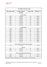
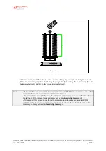
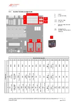
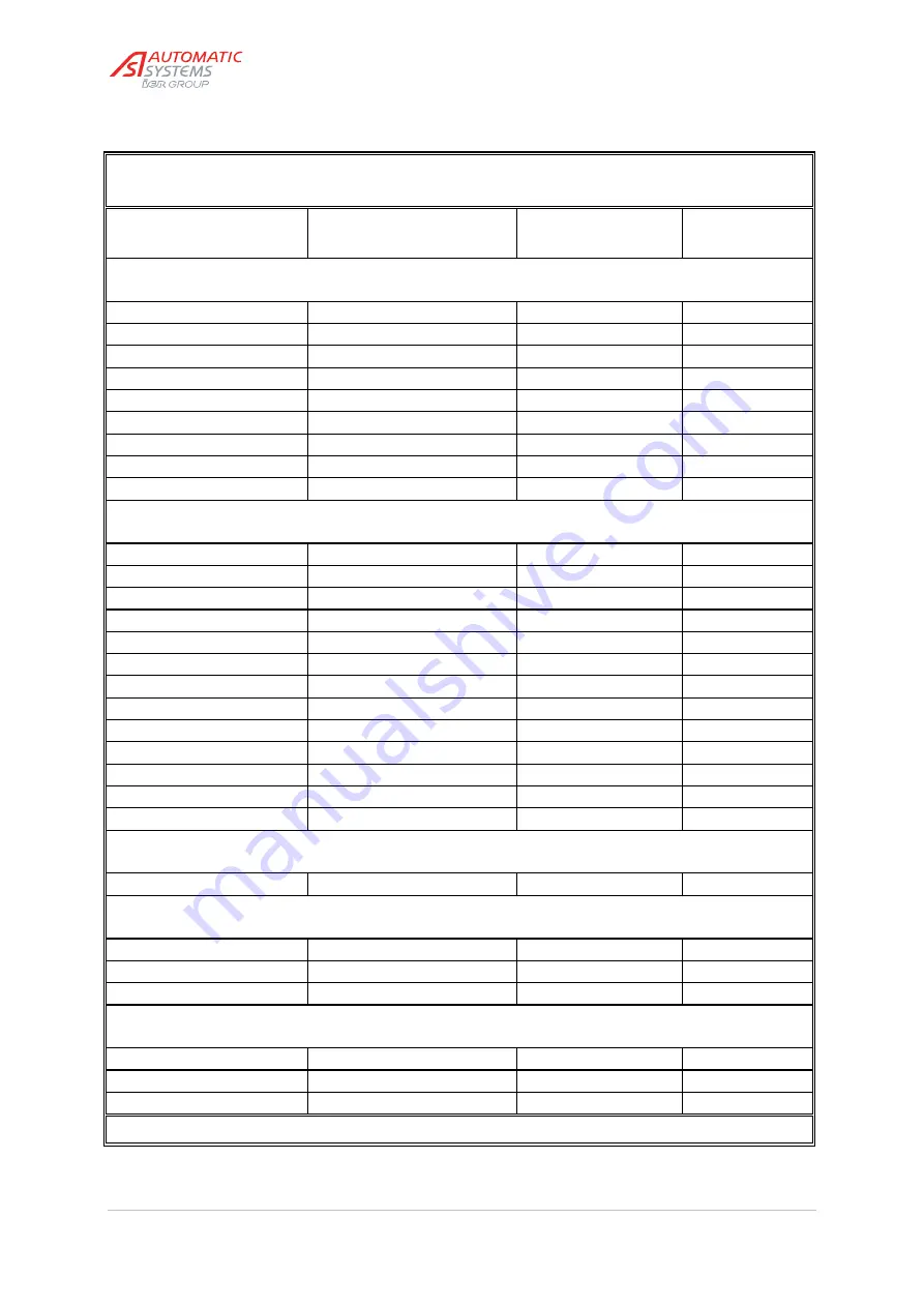
BL32/BL33 balance table
Arm length (up to)
Number and Ø of
springs
Fixing points
Distance "x"
Lateral arm BL32
3.00m
1 x Ø 10mm
A-3
420 mm
3.50m
1 x Ø 10mm
A-3
415 mm
4.00m
2 x Ø 10mm
B-5
395 mm
4.50m
2 x Ø 10mm
B-5
386 mm
5.00m
2 x Ø 10mm
A-3
414 mm
5.50m
2 x Ø 10mm
A-2
406 mm
6.00m
3 x Ø 10mm
B-5
398 mm
6.50m
3 x Ø 10mm
B-5
390 mm
7.00m
3 x Ø 10mm
B-3
384 mm
Central arm BL32
3.00m
1 x Ø 10mm
A-2
395 mm
3.50m
2 x Ø 10mm
B-5
402 mm
4.00m
2 x Ø 10mm
B-3
397 mm
4.50m
2 x Ø 10mm
B-3
384 mm
5.00m
2 x Ø 10mm
A-1
405 mm
5.50m
2 x Ø 10mm
A-1
415 mm
6.00m
3 x Ø 10mm
B-3
386 mm
6.50m
3 x Ø 10mm
A-1
413 mm
7.00m
3 x Ø 10mm
A-1
410 mm
7.50m
3 x Ø 10mm
A-1
400 mm
8.00m
3 x Ø 11mm
A-2
419 mm
8.50m
3 x Ø 11mm
A-1
400 mm
9.00m
3 x Ø 11mm
A-1
409 mm
Central arm BL32 with electromagnetic tip support
4.50m
3 x Ø 11mm
B-5
389mm
BL33 arm
3.00m
3 x Ø 10mm
B-3
400 mm
3.50m
3 x Ø 10mm
A-1
406 mm
4.00m
3 x Ø 10mm
A-1
405 mm
BL33 arm with electromagnetic tip support
3.00m
3 x Ø 10mm
B-3
390 mm
3.50m
3 x Ø 10mm
A-1
411 mm
4.00m
3 x Ø 10mm
A-1
398 mm
Table with most common configurations. Value "x" is spring length with arm in vertical position.


