PNG3XX INSTALLATION MANUAL
NAM-PNG3xx-TM-EN-C.doc
The info rmation contained in this d ocu ment is the p roperty of Auto matic
Syste ms and is co nfidentia l. The re cipient shall refrain fro m using it fo r a ny
purpose other than the use of the pro ducts or the execu tion of the pro ject to
which it refers and fro m co mmunicating it to third partie s without written p rio r
agree ment of Auto matic Syste ms. Do cu ment sub ject to change without notice.
21
Install the electrical power and control cabling as follows:
1. Install power using individual branch circuits to each right and intermediate pedestal: 120VAC with
ground, using 3 conductors – 15Amp, #12 AWG minimum (or to local code).
2. Install a ground wire using #16 AWG (minimum) between left pedestal and intermediate pedestal.
This ensures that all units have a solid ground. Note that, f your using the Belden cable specified in
step 3, it includes the ground.
3. Install the motor interconnect cable between all left and right hand units, including those within an
intermediate pedestal. Use Belden #29500 - 4 #16 AWG copper (w/ 90% braided shield). For
details, see section
4.1.1 Belden 29500
.
4. Install Low Voltage interconnect cable between all left and right hand units, as above. You may
Comtran Corp. type 7110 or Belden #8466 12 conductor #18AWG. See the section 4.1 Low Voltage
Cables. You may also use Belden #83662 for plenum applications without metallic conduit for the
low voltage interconnect. UL equivalent are accepted.
5. Install remote control cables (if optional remote control panel is installed) between control desk and
right (or intermediate) pedestal using 24 #18 AWG (CMP/CLP).
6. Install any other control cables required.
7. Refer to the wiring illustrations at the end of this manual for more information. The Pin-to-pin
connection is represented in Figure 33. The high and low voltage conduit specifications must be
followed.
8. Punch out the conduit entrance holes in the baseplate, if not already done. Make certain that the
anchor bolts you set previously are aligned with the pre punched hole and are protruding from the
baseplate.
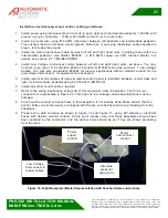
9. Prepare the cable entrance as shown in Figure 16 and Figure 17, using 90º elbows or electrical
boxes with flexible metallic conduit. At this point, please note, that these baseplates should have
been punched by the contractor, and the anchor bolts should be set. They are shown protruding
from the plate.
Figure 16 - Right Baseplate (Master) Representation with Punched Holes and Anchors
Motor
interconnect
conduit
Power
supply
conduit
Low Voltage
interconnect &
reader cables
Alternate
areas for
cable entry

