PNG3XX INSTALLATION MANUAL
NAM-PNG3xx-TM-EN-C.doc
The info rmation contained in this d ocu ment is the p roperty of Auto matic
Syste ms and is co nfidentia l. The re cipient shall refrain fro m using it fo r a ny
purpose other than the use of the pro ducts or the execu tion of the pro ject to
which it refers and fro m co mmunicating it to third partie s without written p rio r
agree ment of Auto matic Syste ms. Do cu ment sub ject to change without notice.
26
2.6 Installation Wiring
2.6.1 Master (Right) Unit
2.6.1.1 Location MF: Master Unit- Inside Front Door
•
Connect the main incoming power supply (120V) into the main power junction box. The power
should be an independent branch circuit using individual neutrals. If acceptable to your AHJ, you
may interrupt power to open the PNG for a fire emergency through a mechanical set of relay
contacts. Please note that electronic interrupters that gradually remove power cannot be used. The
power must be dropped instantly and without a gradual slope for the PNG to open properly.
•
Connect the low voltage interconnect cable to connector X6, in accordance with the appropriate
electrical diagram (See Figure 33).
•
Route the access control cables into the master unit for direction “A” readers and reader outputs
(RTE direction A).
•
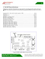
Connect the Access control output to open the PNG for direction A to connection block X13 (see
section 2.7 AS1007 Board (Interface)).
2.6.1.2 Location MR: Master Unit - Inside Rear Door
•
Connect the motor interconnect cable (high voltage interconnect) into the motor junction box. This
junction box is marked 240 V. This marking is for internal use only. No external power is wired to
this. Only the connection cable from the slave motor to the master unit is wired here. The incoming
power is routed trough the main power junction box (see section MF) it is rated 120 V not 240V.
2.6.2 Intermediate Unit – Master Side
2.6.2.1 Location MF: Master Side- Inside Front Door
•
Connect the main incoming power supply (120V) into the main power junction box. The power
should be an independent branch circuit using individual neutrals. If acceptable to your AHJ, you
may interrupt power to open the PNG for a fire emergency through a mechanical set of relay
contacts. Please note that electronic interrupters that gradually remove power cannot be used. The
power must be dropped instantly and without a gradual slope for the PNG to open properly.
•
Connect the low voltage interconnect cable to connector X6, in accordance with the appropriate
electrical diagram (See Figure 33).
•
Route the access control cables into the master unit for direction “A” readers and reader outputs
(RTE direction A).
•
Connect the Access control output to open the PNG for direction A to connection block X13 (see
section 2.7 AS1007 Board (Interface)).


