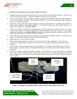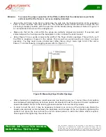
PNG3XX INSTALLATION MANUAL
NAM-PNG3xx-TM-EN-C.doc
The info rmation contained in this d ocu ment is the p roperty of Auto matic
Syste ms and is co nfidentia l. The re cipient shall refrain fro m using it fo r a ny
purpose other than the use of the pro ducts or the execu tion of the pro ject to
which it refers and fro m co mmunicating it to third partie s without written p rio r
agree ment of Auto matic Syste ms. Do cu ment sub ject to change without notice.
28
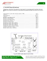
2.7 AS1007 Board (Interface)
Following is a partial list of terminals you may require for connecting specific auxiliary devices to
the PNG. The terminal connections are described and grouped by different sections such as X14 or
X6.
Open direction A: (also called crossing request, or RTE) ............................................X13-1
(Common)...................................................................................................................X13-2
Open direction B ....................................................................................................... X13-11
(Common)................................................................................................................. X13-12
Direction A Controlled (output) ....................................................................................X14-3
Direction A Free (output) .............................................................................................X14-4
Direction A Locked (output) .........................................................................................X14-5
Direction B Controlled (output) ....................................................................................X14-6
Direction B Free (output) .............................................................................................X14-7
Direction B Locked (output) .........................................................................................X14-8
Direction A1 Function (free) command .........................................................................X15-2
Direction A2 Function (lock) command.........................................................................X15-3
Direction B1 Function (free) command .........................................................................X15-4
Direction B2 Function (lock) command.........................................................................X15-5
Fail-Safe emergency open (N.C. jumper) .....................................................................X13-5
Fail-Safe common (N.C. jumper) .................................................................................X13-6
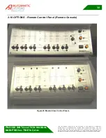
Remote (mode function) Control On ............................................................................X15-1
X-14
X-15
X-13
Lim
it
S
w
itch
es
Low Voltage Cross-Connec t
Ic on B
Ic on A
PLC
PLC
Remote I/O
User
Mode
Figure 20: AS1007 Interface Board Connection Points


