PNG3XX INSTALLATION MANUAL
NAM-PNG3xx-TM-EN-C.doc
The info rmation contained in this d ocu ment is the p roperty of Auto matic
Syste ms and is co nfidentia l. The re cipient shall refrain fro m using it fo r a ny
purpose other than the use of the pro ducts or the execu tion of the pro ject to
which it refers and fro m co mmunicating it to third partie s without written p rio r
agree ment of Auto matic Syste ms. Do cu ment sub ject to change without notice.
37
3.1.2 Detailed Limit Switches Adjustment Procedure.
IMPORTANT: SAFETY INSTRUCTIONS
WARNING – TO REDUCE THE RISK OF INJURY OR DEATH, TURN
OFF THE POWER SUPPLY USING THE CIRCUIT BREAKER PRIOR
TO PERFORMING THE ADJUSTMENT!
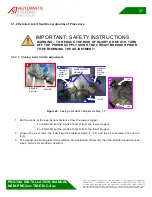
3.1.2.1 Closing Limit Switch Adjustment
2
1
1
2
2
3
3
4
4
5
5
6
6
CAM
LIMIT SWITCH
BRACKET
CLOSING
LIMIT
SWITCH
(CLS)
OPENING
LIMIT
SWITCH
(OLS)
1
SPACER
SPACER
BLOCK
3
OLS
CLS
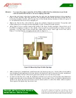
Figure 29
: Closing Limit Switch Adjustment Step 1-3
1. Set the crank at the appropriate distance from the lower stopper.
-
For PNG39X set the crank at 40mm from the lower stopper.
-
For PNG38X set the crank at 30mm from the lower stopper.
2. Loosen the six screws: the 4 limit switch bracket screws (1 to 4) and the 2 set screws in the cam 9
(5-6).
3. The Hybrid unit small glass limit switches are positioned differently than the standard position (see
step 3 picture for standard position).

