background image


Hardware Operations 

1230B0049701


2-12

2.6.4 

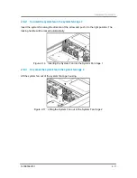
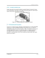
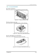
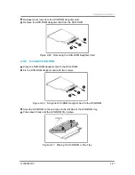
To install the system fan in the system fan cage 2 

Reverse the step above to install the system fans. 


The system fan cage 1 and the system fan cage 2 share many similarities during the removal 

and installation procedures. For your reference, the following is an example using system fan 

cage 1. 


Reminder


Before you remove or install the system fan cage, please follow the steps below: 

Step 1: Make sure the server is not turned on or connected to the AC power. To power off 

the server, see “2.1.1 Power Off”. 

Step 2: Remove the chassis cover. To remove the cover, see “2.2 Chassis Cover”. 

Step 3: Disconnect all necessary cable connections.


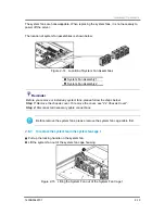
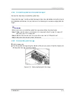
2.6.5 

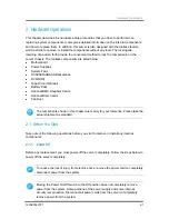
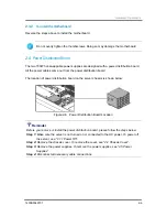
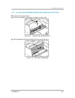
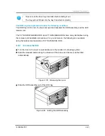
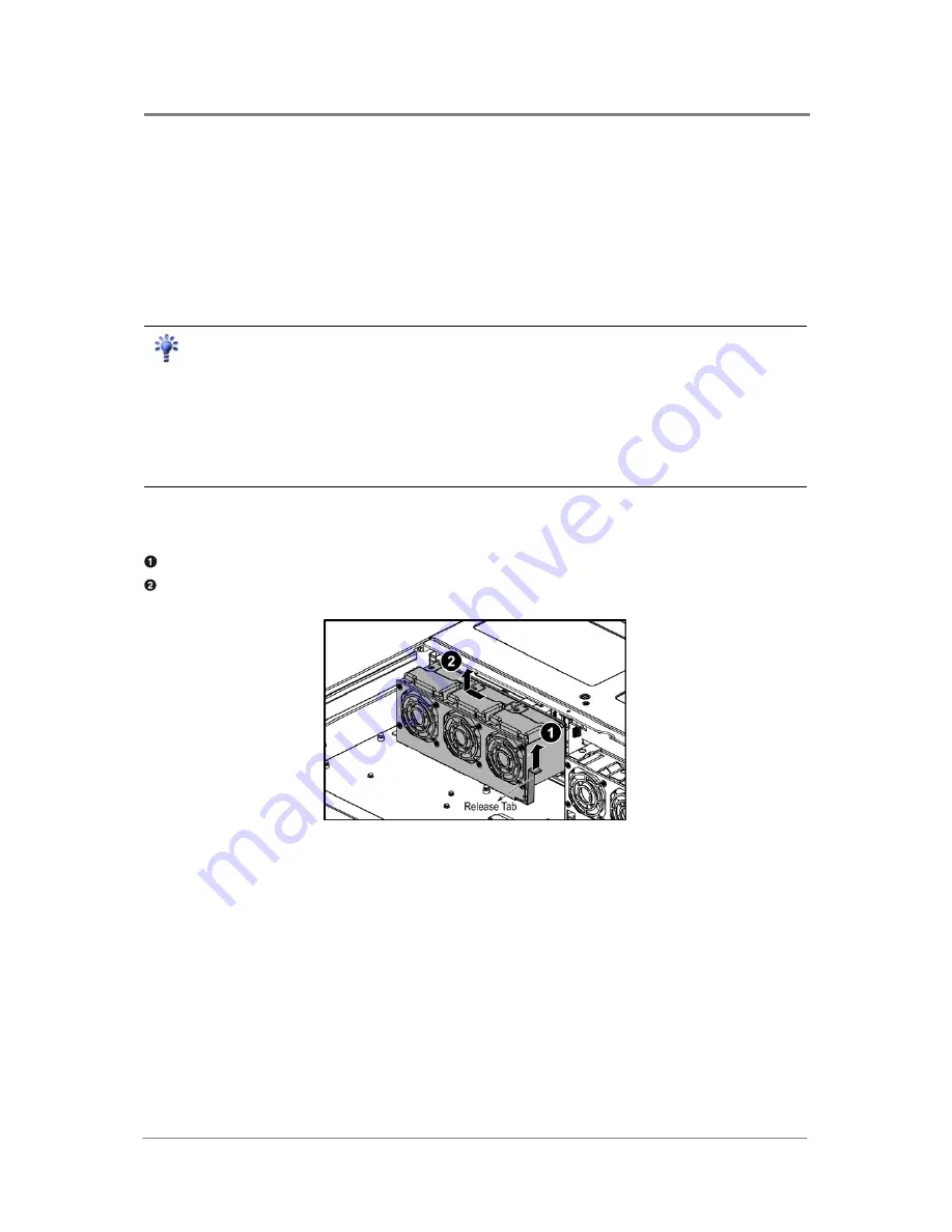
To remove the system fan cage 

  Lift the release tab. 

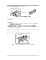
  Push the system fan cage along the direction of the arrow to unlock it from the chassis and 

lift the system fan cage out of the chassis. 


Figure 2-18    Removing the System Fan Cage 

Summary of Contents for ISR2500-6

Page 1: ...2U Server Chassis User Manual ISR2500 6 12H 2410 Aug 2007 Revision A P N 1230B0049701 Regulatory Model No IR2500...

Page 2: ...anual provides the information in relation to the set up and installation of the product herein Nothing herein may be construed as granting any right or license relating to any intellectual property r...

Page 3: ......

Page 4: ...l Organization 1 1 1 3 Packing Checklist 1 2 1 4 Specifications 1 2 1 5 Product Features 1 3 1 6 System Overview 1 6 1 6 1 Server Chassis Layout 1 6 1 6 2 Front View 1 8 1 6 3 Back View 1 9 1 6 4 Butt...

Page 5: ...r 2 5 HDD 2 21 2 7 8 To install the SATAII SAS backplane with expander board for 2 5 HDD 2 22 2 8 SCSI SATAII SAS HDDs 2 22 2 8 1 To remove the HDD 2 23 2 8 2 To install the HDD 2 24 2 9 DVD ROM 2 25...

Page 6: ...4 Power Supply Assembly 3 19 3 5 Power On 3 19 Appendix A Daughter Cards I SCSI Daughter Card with One Channel I SCSI Daughter Card with Two Channels II SAS Daughter Card with One Channel III SAS Daug...

Page 7: ...w of SATAII SAS Backplane with Expander Chip for 3 5 HDD 2 16 Figure 2 23 SATAII SAS Backplane Location 2 17 Figure 2 24 Removing the Backplane and the Backplane Bracket 2 17 Figure 2 25 Removing the...

Page 8: ...apter Card 2 34 Figure 2 66 Removing the Front Panel Bridge Card 2 35 Figure 2 67 Battery Pack Location 2 36 Figure 2 68 Pushing out the ODD Cage 2 36 Figure 2 69 Removing the Battery Pack 2 37 Figure...

Page 9: ...igure 3 14 Connecting the Main Power Cable 3 12 Figure 3 15 Connecting the Processor Power Cable 3 12 Figure 3 16 Connecting the Backplane Power Cable 3 13 Figure 3 17 Connecting the I2 C SMBus Signal...

Page 10: ...le 1 3 Specifications 1 2 Table 1 4 Product Features 1 4 Table 1 5 LED Information 1 12 Appendix Table I 1CH SCSI Daughter Card Information I Appendix Table II 2CH SCSI Daughter Card Information II Ap...

Page 11: ...Conventions Safety Symbols Safety Precautions Regulatory and Integration Information About This Manual...

Page 12: ...e following symbols used throughout this manual Warning Information to prevent injury to yourself when trying to complete a task Caution Information to prevent damage to the components when trying to...

Page 13: ...To reduce the risk of injury from electric shock hazards do not open this enclosure Indicates the presence of a hot surface or hot component Warning To reduce the risk of injury from a hot component...

Page 14: ...Avoid dust humidity and extreme temperatures place the server on a stable surface If the power supply is broken do not try to fix it by yourself Contact an authorized dealer It is recommended that yo...

Page 15: ...touch the antistatic bag and the metal frame of the system unit at the same time Handle the devices carefully to prevent permanent damage Battery Replacement Safety This server is provided with an in...

Page 16: ...al office environment Choose a site that is Clean dry and free of airborne particles other than normal room dust Well ventilated and away from sources of heat including direct sunlight and radiators A...

Page 17: ...ization CENELEC UL 60950 1 Safety of Information Technology Equipment UL 94 Tests for Flammability of Plastic Materials for Parts in Devices Appliances GB4943 Safety of Information Technology Equipmen...

Page 18: ...communications Operation of this equipment in a residential area is likely to cause harmful interference in which case the user will be required to correct the interference at personal expense Declar...

Page 19: ...t marked on the product s electrical ratings label The voltage and current rating of the cord should be greater than the voltage and current rating marked on the product In addition the cross sectiona...

Page 20: ...Audience Assumptions Manual Organization Packing Checklist Specifications Product Features System Overview Chapter 1 Introduction...

Page 21: ...ith the hardware information and how to replace the hardware and connect the cables In addition it provides the detailed information about each type of daughter card in appendix A This manual is gener...

Page 22: ...TAII SAS HDDs Or twelve 2 5 SATAII SAS HDDs Power Cords 1 or 2 power cords Cables SAS HDD cables SCSI HDD cables power supply cables front panel cable USB cable DVD ROM cable and so forth Screws Two t...

Page 23: ...er It includes specific sections that identify these features and specifications The server overview may vary with different types of HDDs Please refer to the picture of each server type shown below F...

Page 24: ...hot pluggable 2 5 HDDs One DVD ROM CD ROM COMBO One FDD Optional One tape drive Optional Backplane SCSI backplane for 3 5 HDD Or SATAII SAS backplane for 3 5 HDD Or SATAII SAS backplane with expander...

Page 25: ...and one PS 2 mouse port BMC Daughter Card Hitachi H8S2167 Or AMI MG9091 Expansion Slot Two expansion slots support Riser card for 2U Chassis with three slots Two PCI E x8 x8 socket and one PCI X 64bit...

Page 26: ...erver Chassis with 3 5 HDD Motherboard Front Panel Adapter Card Fan Duct SCSI SATAII SAS Backplane System Fan Assembly 1 Front Panel Bridge Card Tape Drive Optional System Fan Assembly 2 DVD ROM CD RO...

Page 27: ...therboard Front Panel Adapter Card Fan Duct SATAII SAS Backplane System Fan Assembly 1 Expander Board Tape Drive Optional Front Panel Bridge Card DVD ROM CD ROM COMBO System Fan Assembly 2 Battery Pac...

Page 28: ...with buttons and system LEDs is located on the front According to the different types of HDDs here introduces the front view separately as follows Figure 1 5 Front View HDDs 0 5 Tape Drive Optional HD...

Page 29: ...ial Port Management Port RJ45 SCSI SAS JBOD Connector Optional PS 2 Keyboard Port Rear Dual USB Port PS 2 Mouse Port AC Power Connector 1 D sub VGA Port AC Power Connector 0 This server is designed wi...

Page 30: ...ront panel The front panel status LEDs allow constant monitoring of basic system functions while the server is operating These LEDs provide visual cues to the status of NIC link system fault ID and po...

Page 31: ...Introduction 1230B0049701 1 11 The back view LED information displays details regarding the AC power LEDs Figure 1 9 Back View LEDs AC Power LED 1 AC Power LED 0...

Page 32: ...Need Service by IPMI command or by the ID button Amber Blinking Under Service by the IPMI command ID LED Off Disabled On HDD Present Blue Blinking HDD Data Access On HDD Fault Red Blinking HDD Rebuil...

Page 33: ...on Board Power Supplies System Fan Assemblies SCSI SATAII SAS Backplanes SCSI SATAII SAS HDDs DVD ROM Tape Drive Optional Front Panel Battery Pack Optional BMC Daughter Cards Optional Riser Cards Opti...

Page 34: ...ve Optional Battery Pack Optional BMC Daughter Cards Optional Riser Cards Fan Duct 2 1 Before You Start Take note of the following operations before you start to remove or install any internal compone...

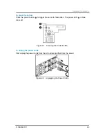
Page 35: ...s the power button to toggle the server to hibernation The power LED in blue turns off Figure 2 1 Pressing the Power Button To unplug the power cords First unplug the power cords from the AC outlets a...

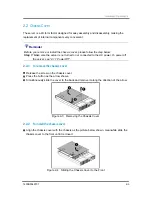
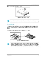
Page 36: ...onnected to the AC power To power off the server see 2 1 1 Power Off 2 2 1 To remove the chassis cover Release the screw on the chassis cover Press the button as the arrow shows Simultaneously slide t...

Page 37: ...d please refer to the Motherboard User Manual The location of motherboard on the server chassis is shown below Figure 2 6 Motherboard Location This unit must be operated with the chassis cover install...

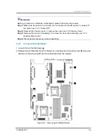
Page 38: ...assis cover To remove the cover see 2 2 Chassis Cover Step 3 Remove the riser card assembly To remove the riser card assembly see 2 14 Optional Riser Cards Step 4 Disconnect all necessary cable connec...

Page 39: ...is is shown below Figure 2 8 Power Distribution Board Location Reminder Before you remove or install the power distribution board please follow the steps below Step 1 Make sure the server is not turne...

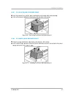
Page 40: ...ibution board along the direction of the arrow Figure 2 9 Removing the Power Distribution Board 2 4 2 To install the power distribution board Place the power distribution board along the direction of...

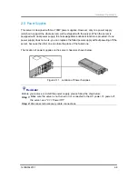
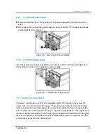
Page 41: ...wer supply does not work you can replace the failed power supply without powering off the server because the other one can take the place of the failed one The location of power supplies on the server...

Page 42: ...the replacement power supply Figure 2 13 Installing the Power Supply 2 6 System Fan Assemblies This server contains two groups of hot swappable system fans seated in the system fan cages which are loc...

Page 43: ...r Before you remove or install any system fans please follow the steps below Step 1 Remove the chassis cover To remove the cover see 2 2 Chassis Cover Step 2 Disconnect all necessary cable connections...

Page 44: ...n of the arrow and push it to the right position The locking handle will be locked automatically Figure 2 16 Inserting the System Fan into the System Fan Cage 1 2 6 3 To remove the system fan in the s...

Page 45: ...e you remove or install the system fan cage please follow the steps below Step 1 Make sure the server is not turned on or connected to the AC power To power off the server see 2 1 1 Power Off Step 2 R...

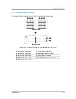
Page 46: ...o the Chassis 2 7 SCSI SATAII SAS Backplanes The server can support four types of backplane SCSI backplane for 3 5 HDD SATAII SAS backplane for 3 5 HDD SATAII SAS backplane with expander chip for 3 5...

Page 47: ...for 3 5 HDD is shown in the picture below Figure 2 20 Front Back View of SCSI Backplane for 3 5 HDD SCSI HDD Connector 0 SCSI HDD Connector 5 SCSI HDD Connector 1 Backplane SCSI Connector SCSI HDD Con...

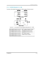
Page 48: ...low Figure 2 21 Front Back View of SATAII SAS Backplane for 3 5 HDD SATAII SAS HDD Connector 0 I2 C SMBus Signal Connector SATAII SAS HDD Connector 1 Backplane SAS Connector 1 SATAII SAS HDD Connector...

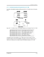
Page 49: ...nnector 0 SATAII SAS HDD Connector 5 SATAII SAS HDD Connector 1 I2 C SMBus Signal Connector SATAII SAS HDD Connector 2 Backplane SAS Connector SATAII SAS HDD Connector 3 3rd Party Connector SATAII SAS...

Page 50: ...not turned on or connected to the AC power To power off the server see 2 1 1 Power Off Step 2 Remove the chassis cover To remove the cover see 2 2 Chassis Cover Step 3 Remove the System Fan Assembly...

Page 51: ...t the backplane bracket with the locking tabs going through the holes on the backplane then push the backplane along the direction of the arrow until it is locked by the locking tab Figure 2 26 Aligni...

Page 52: ...d information please refer to the following section The shape of SATAII SAS backplane for 2 5 HDD is shown in the picture below Figure 2 28 Front Back View of SATAII SAS Backplane for 2 5 HDD SATAII S...

Page 53: ...5 HDD Expander Board Reminder Before you remove or install the SATAII SAS backplane with expander board for 2 5 HDD please follow the steps below Step 1 Make sure the server is not turned on or conne...

Page 54: ...ckplane with expander board for 2 5 HDD Unscrew the expander board Pull out the expander board along the direction of the arrow Figure 2 31 Pulling out the Expander Board Lift the backplane along the...

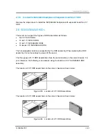
Page 55: ...e 2 5 SATAII SAS HDDs The hot swappable function is supported by the HDD assembly When replacing the HDD assembly it is not necessary to power off the server The three types of 3 5 HDD assemblies shar...

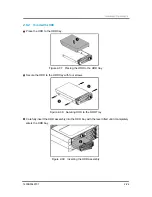
Page 56: ...nce the following is an example using the replacement operation of 3 5 SATAII SAS HDD 2 8 1 To remove the HDD Turn the lock on the lever counterclockwise to the location of unlocking symbol Slide the...

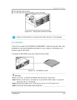
Page 57: ...tray Figure 2 37 Placing the HDD to the HDD tray Secure the HDD to the HDD tray with four screws Figure 2 38 Securing HDD to the HDD Tray Carefully insert the HDD assembly into the HDD bay with the le...

Page 58: ...e following is an example using the DVD ROM The location of DVD ROM on the server chassis is shown below Figure 2 41 DVD ROM Location Reminder Before you remove or install the DVD ROM please follow th...

Page 59: ...out of the chassis Figure 2 42 Pushing out the ODD Cage Lift the locking tab on the side Carefully push the DVD ROM assembly out of the ODD cage Figure 2 43 Pushing out the DVD ROM Assembly Lift the...

Page 60: ...ROM Daughter Card 2 9 2 To install the DVD ROM Place the DVD ROM daughter card to the DVD ROM Fix the DVD ROM daughter card with two screws Figure 2 46 Fixing the DVD ROM Daughter Card to the DVD ROM...

Page 61: ...ROM assembly into the ODD cage until it fits in place Figure 2 48 Inserting the DVD ROM Assembly Carefully insert the ODD cage into the bay Figure 2 49 Inserting the ODD Cage into the Bay Secure the...

Page 62: ...low the steps below Step 1 Make sure the server is not turned on or connected to the AC power To power off the server see 2 1 1 Power Off Step 2 Remove the chassis cover To remove the cover see 2 2 Ch...

Page 63: ...ssembly out of the ODD cage along the direction of the arrow Figure 2 53 Pushing out the Tape Drive Assembly Unscrew the screws as the picture shown below Figure 2 54 Unscrewing the Screws Remove the...

Page 64: ...rive tray Figure 2 56 Putting the Tape Drive into the Tray Secure the tape drive to the tape drive tray with four screws as shown Figure 2 57 Tightening the Screws Push the tape drive assembly into th...

Page 65: ...ge Secure the ODD cage with the thumbscrew Figure 2 60 Securing the ODD Cage 2 11 Front Panel The front panel consists of a front panel adapter card and a front panel bridge card The location of front...

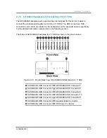
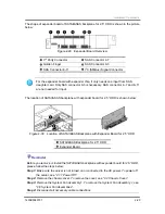
Page 66: ...l Bridge Card Front Panel Adapter Card Connector Front Panel USB Connector Front Panel and IDE Connector Motherboard VGA Connector I2 C Signal Connector Reminder Before you remove or install the front...

Page 67: ...arrow Push the ODD cage and the front panel adapter card out of the chassis Figure 2 64 Pushing out the ODD Cage Loosen the thumbscrew on the adapter card Pull out the adapter card along the direction...

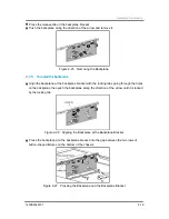
Page 68: ...emove the front panel bridge card from the chassis along the direction of the arrow Figure 2 66 Removing the Front Panel Bridge Card 2 11 2 To install the front panel Reverse the steps above to instal...

Page 69: ...pack please follow the steps below Step 1 Make sure the server is not turned on or connected to the AC power To power off the server see 2 1 1 Power Off Step 2 Remove the chassis cover To remove the c...

Page 70: ...moving the Battery Pack 2 12 2 To install the battery pack Place the battery pack along the direction of the arrow Align the poles on the battery to the holes on the ODD cage then insert it Figure 2 7...

Page 71: ...H8S2167 and AMI MG9091 The BMC daughter card is designed to plug into the BMC daughter card slot vertically to fit in the chassis The two BMC daughter cards share many similarities during the removal...

Page 72: ...daughter card Reverse the step above to install the BMC daughter card 2 14 Optional Riser Cards The motherboard provides two expansion slots The expansion slot 1 can support the riser card with two fu...

Page 73: ...8 socket PCI X Expansion Slot The riser card for expansion slot 2 is shown below Figure 2 76 Riser Card for Expansion Slot 2 Golden Fingers PCI E x8 x8 socket PCI E x4 x8 socket The two riser cards sh...

Page 74: ...1 Make sure the server is not turned on or connected to the AC power To power off the server see 2 1 1 Power Off Step 2 Remove the chassis cover To remove the cover see 2 2 Chassis Cover Step 3 Disco...

Page 75: ...n Card Press the locking tab Push the riser card along the direction of the arrow and lift it up Figure 2 80 Removing the Riser Card 2 14 2 To install the riser card Reverse the steps above to install...

Page 76: ...er card uses the specific chipset for optimal features and provides expansive storage by connecting with the additional devices This section provides the locations removal and installation steps of th...

Page 77: ...r card assembly To remove the riser card assembly see 2 14 Optional Riser Cards Step 4 Disconnect all necessary cable connections The SCSI daughter card and the SAS daughter card share many similariti...

Page 78: ...2 84 Installing the Daughter Card Assembly When installing the SAS RAID daughter card with two channels LSI1078 SAS daughter card a daughter card latch is necessary to fix it tightly For the removal a...

Page 79: ...plastic pole and then carefully insert it Figure 2 86 Installing the Daughter card Latch When installing the SAS RAID daughter card with two channels LSI1078 SAS daughter card an I button is necessar...

Page 80: ...2 15 5 To remove the I button Push aside the two locking clips Lift the I button out of the socket Figure 2 88 Removing the I button 2 15 6 To install the I button Locate the I button into the socket...

Page 81: ...below Step 1 Make sure the server is not turned on or connected to the AC power To power off the server see 2 1 1 Power Off Step 2 Remove the chassis cover To remove the cover see 2 2 Chassis Cover 2...

Page 82: ...Cable List Connectors and Pin 1 Locations Cable Connections Power Supply Assembly Power On Chapter 3 Cable Connections...

Page 83: ...necessary cable connections for 2U server 3 1 Cable List The list below shows all the cables shipped with the machine According to the list you can have a general idea of the cables and check if there...

Page 84: ...701 3 2 3 2 Connectors and Pin 1 Locations The figure below shows the different locations of necessary connectors and their pin 1 location which can make you easily connect the cables Figure 3 2 Locat...

Page 85: ...igures showing cable locations and descriptions of the connection procedures This section shows all the cable connections associated with the server supporting SCSI SATAII SAS backplanes for 3 5 HDD a...

Page 86: ...ns among different types of backplanes daughter cards JBODs and HDDs SCSI Backplane for 3 5 HDD Figure 3 4 Front Back View of SCSI Backplane for 3 5 HDD For the detailed information about the connecto...

Page 87: ...Cable Connections 1230B0049701 3 5 Connection Method for SCSI Backplane of 3 5 HDD SATAII SAS Backplane for 3 5 HDD Figure 3 5 Front Back View of SATAII SAS Backplane for 3 5 HDD...

Page 88: ...Connections 1230B0049701 3 6 Connection Method for SATAII SAS Backplane of 3 5 HDD SATAII SAS Backplane with Expander Chip for 3 5 HDD Figure 3 6 Front Back View of SATAII SAS Backplane with Expander...

Page 89: ...0B0049701 3 7 Connection Method for SATAII SAS Backplane with Expander Chip of 3 5 HDD SATAII SAS Backplane with Expander Board for 2 5 HDD Figure 3 7 SATAII SAS Backplane for 2 5 HDD Figure 3 8 Expan...

Page 90: ...Cable Connections 1230B0049701 3 8 Connection Method for SATAII SAS Backplane with Expander Board of 2 5 HDD...

Page 91: ...ont panel bridge card Figure 3 9 Connecting the Front Panel Cable In this subsection the front panel adapter card front panel bridge card and several types of connectors which may cause confusion will...

Page 92: ...el I2 C signal cable to the front panel I2 C connector on the front panel bridge card Connect the other end of the front panel I2 C signal cable to the I2 C SMBus signal connector on the backplane for...

Page 93: ...t panel VGA cable to the front panel VGA connector on the front panel bridge card Figure 3 12 Connecting the Front Panel VGA Cable to the Bridge Card Connect one end of the front panel VGA cable to th...

Page 94: ...able from the power supply to the main power connector on the motherboard Figure 3 14 Connecting the Main Power Cable Processor Power Cable Connect the 8 pin processor power cable from the power suppl...

Page 95: ...B 6 pin of the HDD backplane power cable to the HDD power cable from the power supply and connector C 6 pin of the HDD backplane power cable to the power connector on the backplane Figure 3 16 Connec...

Page 96: ...motherboard Figure 3 17 Connecting the I2 C SMBus Signal Cable for Power Supply 3 3 6 DVD ROM Cable Connect one end of the DVD ROM cable to the connector on the front panel adapter card Connect the o...

Page 97: ...e other end of the FDD cable to the corresponding connector on the FDD Figure 3 19 Connecting the FDD Cable 3 3 8 USB FDD Cable Connect one end of the USB FDD cable to the USB FDD connector on the mot...

Page 98: ...power cable for tape drive to the connector on the tape drive Figure 3 21 Connecting the SATA Power Cable for Tape Drive 3 3 10 System Fan Cables System Fan Tach Cable Connect one end of the system f...

Page 99: ...1 3 17 System Fan Power Cable For the connectors of system fan cage 1 and system fan cage 2 please refer to the figure below Figure 3 23 System Fan Connector Location Connector of System Fan Cage 2 Co...

Page 100: ...ble to connector A 4 pin of the HDD backplane power cable Connect connector B 6 pin of the HDD backplane power cable to the HDD power connector from the power supply Figure 3 24 Connecting the System...

Page 101: ...on the server make sure that you have completed the basic system connections Follow these steps when starting the server Step 1 Monitor Connection Connect a monitor by plugging a video cable to the V...

Page 102: ...for Powering On PS 2 Keyboard Port AC Power Connector 1 PS 2 Mouse Port AC Power Connector 0 D sub VGA Port Step 6 Power On Press the power button on the front panel to toggle the server to power on T...

Page 103: ...Daughter Cards China RoHS Regulations Appendix...

Page 104: ...x Figure I 1CH SCSI Daughter Card Appendix Table I 1CH SCSI Daughter Card Information Chip LSI Logic 53C1020 Functional Brief Ultra320 PCI X SCSI RAID RAID IS IM IME Storage Interface One SCSI 68 pin...

Page 105: ...ughter Card Channel A CHA Channel B CHB Appendix Table II 2CH SCSI Daughter Card Information Chip Adaptec AIC 7902W Functional Brief Ultra320 PCI X SCSI RAID RAID RAID 1 0 10 Storage Interface Two SCS...

Page 106: ...nel Appendix Figure III 1CH SAS Daughter Card Appendix Table III 1CH SAS Daughter Card Information Chip LSI 1064E Functional Brief SAS PCI E RAID RAID IS IM IME Storage Interface HDD fault LED signal...

Page 107: ...V 2CH SAS Daughter Card Channel B CHB Port 4 7 Channel A CHA Port 0 3 Appendix Table IV 2CH SAS Daughter Card Information Chip LSI 1068E Functional Brief SAS PCI E RAID RAID IS IM IME Storage Interfac...

Page 108: ...Figure V 2CH SAS RAID Daughter Card Channel B CHB Port 4 7 Channel A CHA Port 0 3 Appendix Table V 2CH SAS RAID Daughter Card Information Chip LSI 1078E Functional Brief SAS PCI E RAID RAID RAID 1 0 1...

Page 109: ...Appendix 1230B0049701 VI Appendix B China RoHS Regulations Appendix Figure VI China RoHS Regulations...

Reviews: