
iesy GmbH
www.iesy.com | sales@iesy.com | Tel.: +49 (2354) 70655 0
Local court Iserlohn | HRA 9826 |
USt-IdNr
: DE339671635 | Managing Director: Dipl.-Ing. Martin Steger
Seite 22 von 27
User Manual V-180131-BHA00
7
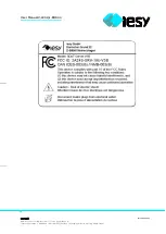
FCC Compliance
FCC ID: 2AZ4S-SRV-19U-V3B
CAN ICES-003(B) / NMB-003(B)
„This device complies with part 15 of the FCC Rules. Operation is subject to the following two
conditions: (1) this device may not cause harmful interference, and (2) this device must accept any
interference received, including interference that may cause undesired operation.“
The FCC ID nameplate is attached to the rear of the housing near the power supply. The label
contains additional notes and warnings. The type plate must not be removed!
This equipment has been tested and found to comply with the limits for a Class B digital device,
pursuant to part 15 of the FCC Rules. These limits are designed to provide reasonable protection
against harmful interference in a residential installation. This equipment generates, uses and can
radiate radio frequency energy and, if not installed and used in accordance with the instructions,
may cause harmful interference to radio communications. However, there is no guarantee that
interference will not occur in a particular installation. If this equipment does cause harmful
interference to radio or television reception, which can be determined by turning the equipment off
and on, the user is encouraged to try to correct the interference by one or more of the following
measures:
Reorient or relocate the receiving antenna.
Increase the separation between the equipment and receiver.
Connect the equipment into an outlet on a circuit different from that to which the receiver is
connected.
consult the dealer or an experienced radio/TV technician for help
Any changes or modifications made to the device not expressly approved by the party responsible
for compliance may void the user’s authority to operate the equipment.


