background image

iesy GmbH 
www.iesy.com  |  sales@iesy.com  |  Tel.: +49 (2354) 70655 0 

Local court Iserlohn  |  HRA 9826  |  

USt-IdNr

: DE339671635  |  Managing Director: Dipl.-Ing. Martin Steger


Seite 7 von 27 

User Manual V-180131-BHA00 


1.9


Modifications and Structural Changes 

The  system  may  not  be  modified  in  terms  of  design  or  safety  without  our  express  consent.  Any 
modification excludes liability on our part for any resulting damage. In particular, any repairs, soldering 
work  on  the  circuit  boards  (replacement  of  components)  are  prohibited.  When  replacing  entire 
assemblies, only original parts are to be used. The system was delivered from the factory with a fixed 
hardware  configuration.  Modifications  are  only  permitted  within  the  scope  of  the  possibilities 
documented in the manuals. 

1.10


Qualified Personnel 

This  appliance  may  only  be  used  by  qualified  personnel  and  only  in  accordance  with  the  technical 
data in connection with the safety rules and regulations listed below. Qualified personnel are persons 
who  are  familiar  with  the  installation,  assembly,  commissioning  and  operation  of  the  product  and 
have the  qualifications appropriate to their job. This includes  persons  who  meet at least  one of the 
following three requirements: 


the persons are familiar with the safety concepts of IT / automation technology and are familiar 
with them as project personnel 


the persons are operators of the IT / automation systems and have been instructed in the use 
of the systems and IT systems. They are familiar with the operation of the modules and 
technologies described in this documentation 


the persons are commissioning engineers or assigned for service and have completed training 
that qualifies them to repair IT / automation systems. They are also authorised to commission, 
earth and label circuits and equipment in accordance with safety engineering standards. During 
use,  the  legal  and  safety  regulations  required  for  the  respective  application  must  also  be 
observed. This also applies to the use of accessories. Maintenance and repair work on the open, 
live unit may only be carried out by a trained person who is aware of the danger involved 


Summary of Contents for SDoT Server V3B

Page 1: ...User Manual Document V 180131 BHA00 Project User Manual SDoT Server V3B Date 20 09 2021...

Page 2: ...ide 6 1 7 Service and Cleaning 6 1 8 Product Liability 6 1 9 Modifications and Structural Changes 7 1 10 Qualified Personnel 7 1 11 Symbols and Meanings 8 2 Assembly SDoT Server V3B 9 3 Connection SDo...

Page 3: ...ector Dipl Ing Martin Steger Seite 3 von 27 User Manual V 180131 BHA00 4 2 Starting the SDoT Server V3B 17 4 3 LC Touchdisplay T1 18 4 4 Shutdown and Restart 20 5 Waste disposal and Environmental prot...

Page 4: ...ust be taken for systems that could cause major damage loss of data or even personal injury due to a malfunction In the event of a malfunction these precautions will ensure a safe operating condition...

Page 5: ...urrent protection device for the unit The highest rated value of this device is 16A 1 5 Battery Change optional The SDoT servers V3B have a battery compartment on the back of the 19 housing It is only...

Page 6: ...slightly damp cloth Never use solvents as these could damage the labelling or the housing When cleaning make sure that no liquid gets into the module or onto the connections The fans and the redundan...

Page 7: ...personnel are persons who are familiar with the installation assembly commissioning and operation of the product and have the qualifications appropriate to their job This includes persons who meet at...

Page 8: ...ronic components against electrostatic discharge precautions must be taken such as suitable work clothing dissipative floor coverings a grounding strap etc Symbol Meaning Federal Communications Commis...

Page 9: ...ting rails can be used to allow the unit to be pulled out of an IT cabinet for operation The SDoT Server V3B 10G SC variant shown below has a smartcard slot and two 10 Gbit network ports N5 N6 Optiona...

Page 10: ...7 User Manual V 180131 BHA00 3 Connection SDoT Server V3B The AC power supply should be located close to the device and easily accessible as this serves as a disconnecting device for the device Altern...

Page 11: ...ess the black locking lever in the direction of the bow handle 4 while holding the lever pull the power supply out of the housing by the metal bracket 5 check that the replacement power supply corresp...

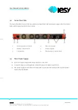
Page 12: ...onnection to HIGH interface up to 1 Gbit N2 Network connection to LOW interface up to 1 Gbit N3 Mains connection to HEARTBEAT interface N4 Network connection to ADMIN interface N5 Network connection t...

Page 13: ...t and two power supply units the slide in bolts and the openings for the fan module 1 2 3 Insertion bolt in 19 Rack Battery compartment Fan module 4 5 6 Mass fan module Power supplies Manufacturer s d...

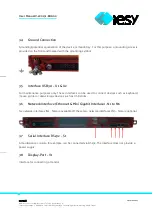
Page 14: ...the grounding symbol 3 5 Interface USB3 0 U1 U2 For maintenance purposes only These interfaces can be used to connect devices such as keyboard mouse printer or data storage devices such as USB sticks...

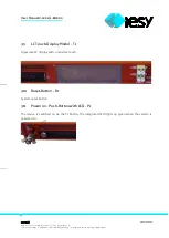
Page 15: ...Dipl Ing Martin Steger Seite 15 von 27 User Manual V 180131 BHA00 3 9 LC Touch Display Modul T1 Grayscale LC display with a resistive touch 3 10 Reset Button R1 System reset button 3 11 Power on Push...

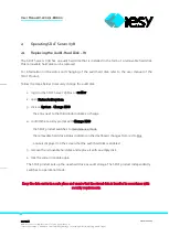
Page 16: ...audit disk 1 log in to the SDoT Server V3B as an auditor 2 open Status Audit system 3 click on System Change HDD the entry next to the third diode indicates a change 4 confirm the security prompt with...

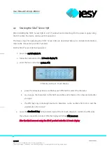
Page 17: ...DoT Server V3B into operation 1 press the on off switch P1 2 follow the indication of the LC touch display T1 3 enter the four or six digit system PIN PIN Entry on the LC Touch Display a press the arr...

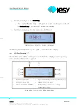
Page 18: ...ch display shows the start screen of the SDoT Product Startup Display of the SDoT Product exemplary The following describes the meaning of the symbols used on the LC touch display 4 3 LC Touchdisplay...

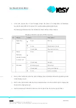
Page 19: ...for operation HSM SC and HA No Display Symbol Description 1 Operating status Cross Boot up Circle Maintenance mode Checkmark Operational mode 2 Status hardware security module or smartcard Cross Incor...

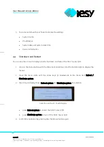
Page 20: ...can use the LC touch display to both shut down and restart the SDoT Server V3B 1 click on the menu button with the three horizontal lines 7 at the bottom right to display the menus 2 move the menu it...

Page 21: ...is no longer usable in accordance with European regulations for environmental protection and raw material recovery must be disposed of separately from regular household waste Since disposal regulatio...

Page 22: ...o provide reasonable protection against harmful interference in a residential installation This equipment generates uses and can radiate radio frequency energy and if not installed and used in accorda...

Page 23: ...iesy GmbH www iesy com sales iesy com Tel 49 2354 70655 0 Local court Iserlohn HRA 9826 USt IdNr DE339671635 Managing Director Dipl Ing Martin Steger Seite 23 von 27 User Manual V 180131 BHA00...

Page 24: ...GmbH www iesy com sales iesy com Tel 49 2354 70655 0 Local court Iserlohn HRA 9826 USt IdNr DE339671635 Managing Director Dipl Ing Martin Steger Seite 24 von 27 User Manual V 180131 BHA00 8 Block dia...

Page 25: ...von 27 User Manual V 180131 BHA00 9 Technical data Type SDoT Server V3B Operating voltage 100 240 VAC Frequency 50 60 Hz Current consumption max 5 A Unom 230 VAC Fnom 50 Hz Inom 0 4 A Temperature ope...

Page 26: ...iesy com sales iesy com Tel 49 2354 70655 0 Local court Iserlohn HRA 9826 USt IdNr DE339671635 Managing Director Dipl Ing Martin Steger Seite 26 von 27 User Manual V 180131 BHA00 10 Dimensions mm SDo...

Page 27: ...ocal court Iserlohn HRA 9826 USt IdNr DE339671635 Managing Director Dipl Ing Martin Steger Seite 27 von 27 User Manual V 180131 BHA00 11 Revision Tracking Date Revision Consultant Manufacturer Discrip...

Reviews: