Page 98 of 110
Theory
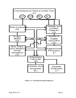
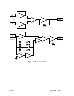
For the detection circuitry this includes the reference resistor, the gain in the current and voltage
detectors, and analog filtering optimized for the frequency of excitation. There are five reference
resistors, each of which covers an impedance range of 15:1, and 5:1 at the lowest impedance.
The reference resistor is normally chosen by the embedded computer to match the impedance of
the unknown as closely as possible. However, the user may override this function, which can
improve measurement speed in specialized applications. Gain in the voltage detector and current
detector is normally chosen by the embedded computer to optimize the performance of the
digitization process. The optimum gain in both detectors depends on excitation level, frequency
and DUT impedance. As with the reference resistor, this can be overridden by the user.
The embedded computer also controls measurement speed. There are three settings for
measurement accuracy: High (1 measurement per second), Medium (10 Measurements per
second), and Low (40 measurements per second). These times can be lengthened somewhat
depending on the frequency of excitation, averaging, median, and other conditions. The
embedded computer also controls the local user interface (keyboard and display), and the remote
interfaces (RS-232, IEEE-488 and handler interface).
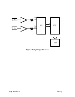
A separate Digital Signal Processor (DSP) performs the high-speed calculations inherent in the
measurement technique. The DSP computes the real and imaginary components of impedance,
and converts these into Capacitance (Cs/Cp), Inductance (Ls/Lp), Resistance (Rs/Rp),
Dissipation (DF) and Quality (Q) Factors, Impedance (|Z|), Admittance |Y|, Phase Angle (
),
Equivalent Series Resistance (|ESR|), Conductance (Gp), Reactance (Xs), Susceptance (Bp). Any
two parameters can be measured and displayed simultaneously. In the above parameters the
subscript s denotes series equivalent circuit, while subscript p denotes parallel equivalent circuit.
Summary of Contents for 1910
Page 8: ...Page 4 of 110...
Page 10: ...Page 6 of 110...
Page 34: ......
Page 100: ......
Page 107: ...Theory Page 103 of 110 Figure 4 4 Detector Circuits Es IL Ex PL PH Voltage Current...
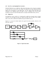
Page 108: ...Page 104 of 110 Theory Figure 4 5 Digital Signal Processor Es Ex CPU DSP A D Vin A Vin B...

