Page 100 of 110
Theory
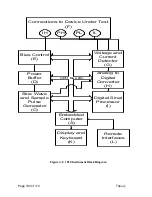
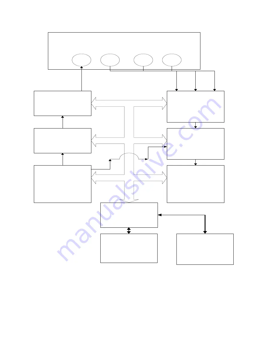
Figure 4-1: 1910 Instrument Block Diagram
Connections to Device Under Test
(F)
Embedded
Computer
(A)
Display and
Keyboard
(K)
Remote
Interfaces
(L)
Digital Sinal
Processor
(I)
Sine Wave
and Sample
Pulse
Generator
(C)
Power
Buffer
(D)
Bias Control
(E)
Voltage and
Current
Detector
(G)
Analog to
Digital
Converter
(H)
CPU Bus (B)
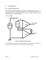
IH
PH
PL
IL
Summary of Contents for 1910
Page 8: ...Page 4 of 110...
Page 10: ...Page 6 of 110...
Page 34: ......
Page 100: ......
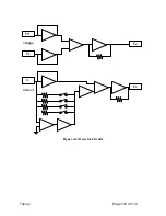
Page 107: ...Theory Page 103 of 110 Figure 4 4 Detector Circuits Es IL Ex PL PH Voltage Current...
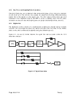
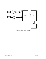
Page 108: ...Page 104 of 110 Theory Figure 4 5 Digital Signal Processor Es Ex CPU DSP A D Vin A Vin B...

