Page 34 of 110
Introduction
1.5 Installation
1.5.1 Dimensions
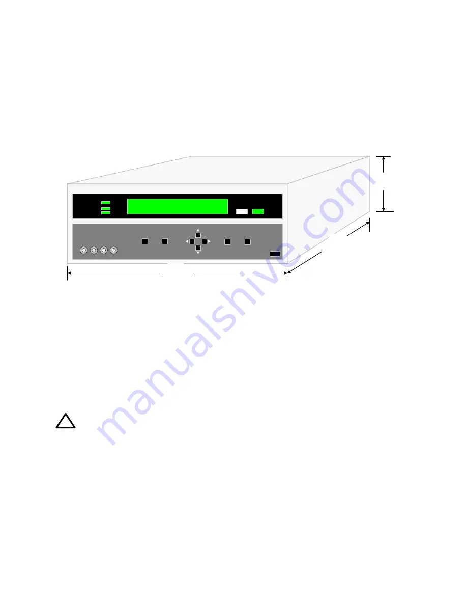
The 1910 Inductance Analyzer is supplied in a bench configuration, i.e. in a cabinet with
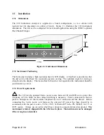
resilient feet for placement on a table or bench. Figure 1.3 illustrates the 1910 instrument
dimensions. The unit can be configured for rack mount applications using the 2000-16 optional
Rack Mount Flanges.
IET
1910
Inductance Analyzer
IET Labs
Model 1910 V1.4
17 in
432mm
16 in
406mm
5 in
133mm
Figure 1-3: Instrument Dimensions
1.5.2 Instrument Positioning
The front panel includes a high resolution back lit LCD display. A front bail is provided so that
the unit can be tilted back for convenient operator viewing. The optimum angle for viewing is
straight onto the display. This means that for bench or rack operation the instrument should be
positioned at eye level.
1.5.3 Power Requirements
!
The 1910 can be operated from a power source between 100 and 240Vac at a power line
frequency of 50 to 60Hz, no line voltage switching is necessary. Power connection to the rear
panel is through an AC inlet module comprised of an AC connector and fuse drawer. Before
connecting the 3-wire power cord between the unit and AC power the fuses should be in
accordance with the power source, T2.5A, 250V, 5x20mm (IET Labs. PN 520049) for 115 or
220V source. Always use an outlet which has a properly connected protection ground.
The
instrument is factory shipped with the 2.5A fuse in place. The instrument can be damaged
if the wrong fuse is installed.
Summary of Contents for 1910
Page 8: ...Page 4 of 110...
Page 10: ...Page 6 of 110...
Page 34: ......
Page 100: ......
Page 107: ...Theory Page 103 of 110 Figure 4 4 Detector Circuits Es IL Ex PL PH Voltage Current...
Page 108: ...Page 104 of 110 Theory Figure 4 5 Digital Signal Processor Es Ex CPU DSP A D Vin A Vin B...

