background image


PRECISION INSTRUMENTS FOR TEST AND MEASUREMENT


Email: info@ietlabs.com

TEL:  (516) 334-5959 • FAX: (516) 334-5988

www.ietlabs.com

IET LABS, INC.

1863 and 1864

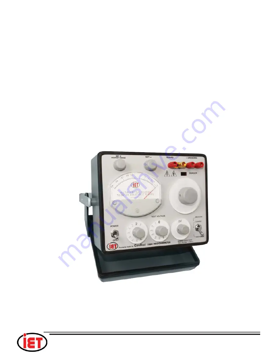
Megohmmeters

User and Service Manual

Copyright © 2018 IET Labs, Inc.

Visit www.ietlabs.com for manual revision updates

1863-1864 im/Aug 2018

Summary of Contents for 1863

Page 1: ...EMENT Email info ietlabs com TEL 516 334 5959 FAX 516 334 5988 www ietlabs com IET LABS INC 1863 and 1864 Megohmmeters User and Service Manual Copyright 2018 IET Labs Inc Visit www ietlabs com for man...

Page 2: ...om IET LABS INC Revision History Date Description By 7 28 10 Corrected Errors Automatic TOC created LB 5 25 11 Corrected input output identification error on Page 4 Voltage range on page 4 was 200 230...

Page 3: ...at no charge when returned to IET Changes in this product not approved by IET or application of voltages or currents greater than those allowed by the specifications shall void this warranty IET shall...

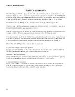
Page 4: ...E USED TAKE ALL MEASURES TO AVOID ACCIDENTAL CONTACT WITH ANY LIVE COMPONENTS USE MAXIMUM INSULATION AND MINIMIZE THE USE OF BARE CONDUCTORS WHEN USING THIS INSTRUMENT Use extreme caution when working...

Page 5: ...ions 6 Chapter 2 INSTALLATION 7 2 1 Initial Inspection 7 2 2 Dimensions 7 2 3 Repackaging for Shipment 7 2 4 Storage 8 2 5 Bench Setup 8 2 6 Rack Mounting 8 2 7 Power Connections 8 Chapter 3 OPERATION...

Page 6: ...4 6 Guarded 3 Terminal Measurements 16 4 7 Remote Shielded Measurements 17 4 8 Measurements Under Humid Conditions 17 Chapter 5 THEORY 19 5 1 Theory Overview 19 5 2 Circuit Description 19 5 2 1 Type...

Page 7: ...lock diagram 20 Figure 6 1 Connections for measuring standard resistors 22 Figure 6 2 Top interior view of 1863 Megohmmeter 25 Figure 6 3 Bottom interior view of 1863 Megohmmeter 25 Figure 6 4 Top int...

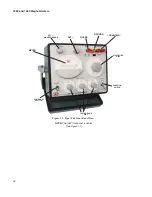
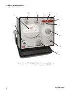
Page 8: ...ommeters iv Figure 1 1 Type 1864 Front Panel View NOTE The 1863 front panel is similar See Figure 1 2 SET HIGHEST RANGE SET GUARD UNKNOWN GROUND MULTIPLIER DIAL FUNCTION SWITCH TEST VOLTAGE DIAL POWER...

Page 9: ...unknown resistor to the UNKNOWN terminals 9 Set the function switch to the CHARGE position and pause for a few seconds If the sample has a large capacitance charging time has to be increased accordin...

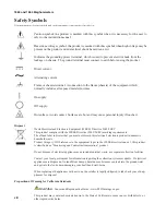
Page 10: ...Megohmmeter If an instrument is marked CAT I IEC Measurement Category I or it is not marked with a measurement category its measurement terminals must not be connected to line voltage mains and it is...

Page 11: ...rs Component replacement and internal adjustments must be made by qualified maintenance personnel only DO NOT substitute parts or modify the instrument There are no user serviceable parts inside Refer...

Page 12: ...WEEE Directive 2002 96 EC This product complies with the WEEE Directive 2002 96 EC marking requirements The affixed label indicates that you must not discard this electrical electronic product in dome...

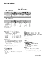
Page 13: ...rdg 10 Vdc to 50 Vdc 50 k 500 G 2 T 7 50 Vdc to 100 Vdc 200 k 5 T 20 T 8 100 Vdc to 500 Vdc 500 k 5 T 20 T 7 500 Vdc to 1090 Vdc 5 M 50 T 200 T 8 Recommended Limit Rmin Full Scale left end 0 5 rdg Rm...

Page 14: ...rective 2002 96 EC marking requirements The affixed label indicates that you must not discard this electrical electronic product in domestic household waste Product Category With reference to the equi...

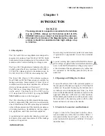
Page 15: ...resistance from 50 k to 200 T Both instruments feature an analog meter for readout of the resistance and a built in floating dc voltage source The Type 1863 Megohmmeter indicates directly on an analo...

Page 16: ...1863 and 1864 Meghommeters 2 INTRODUCTION Figure 1 2 Type 1863 Front panel Controls Connectors and Indicators 1 2 3 4 5 6 7 8 9 10 11 12...

Page 17: ...1863 and 1864 Meghommeters 3 INTRODUCTION Figure 1 2 B Type 1864 Front panel Controls Connectors and Indicators 1 2 3 12 10 5 6 7 8 9 4 11...

Page 18: ...1863 and 1864 Meghommeters 4 INTRODUCTION...

Page 19: ...receptacle Power input and circuit protection 2 Output X X Phone jack Provides a dc voltage output for recorder or DMM 3 Line Voltage X X 2 position slide switch Connects wiring of power transformer f...

Page 20: ...3 M 1 T 1012 109 k 106 M 103 G 1 5 Connections The UNKNOWN GUARD and ground terminals are standard 3 4 in spaced binding posts that accept banana plugs standard telephone tips alligator clips crocodil...

Page 21: ...ckaging for Shipment If the instrument is to be returned to IETLabs contact the Service Department at the number or address shown on the front cover of this manual to obtain a Returned Material Author...

Page 22: ...ze fuse for the input voltage selected has been installed 1 4 A slow blow for 100 125 V input or 1 8 A slow blow for 200 250 V input To change the fuse proceed as follows Proce dure 1 Make sure the un...

Page 23: ...make sure the toggle switch is set to DISCHARGE for safety This terminates the high voltage being applied to the output terminals and discharges the DUT 5 When the red DANGER light is lit NEVER touch...

Page 24: ...ng storage and shipping please use packaging that is adequate to protect it from damage i e equivalent to the original packaging and mark the box Delicate Elec tronic Instrument Please follow online i...

Page 25: ...ting link When capacitors are tested there is an especially dangerous condition because a charged capacitor can have enough energy to cause heart fibrillation and death The capacitor should always be...

Page 26: ...unction switch is set to DISCHARGE 2 Make sure that nothing is connected to the UNKNOWN terminals 3 Turn the instrument on 4 Set the multiplier dial to any range 5 Adjust the SET control for an readin...

Page 27: ...on switch to DISCHARGE and wait a few seconds 11 DisconnectthesamplefromtheUNKNOWN terminals For best accuracy and resolution before taking the final reading recheck the initial adjustments section 3...

Page 28: ...RANGE is the lower value for a particular multiplier dial set ting 100k for the 1 M 100 k range and Rx is the value of the resistance being measured The output can be stored in a data file for plot ti...

Page 29: ...edure described in Section 3 MIL STD 202C gives procedures for insulation resistance measurements of various components On large machinery one terminal must usually be grounded The Megohmeter is desig...

Page 30: ...ume and several minutes hours or even days are required for equilibrium in order to make the charging cur rent small compared with the true leakage current A measure of this effect called the Polariza...

Page 31: ...e 4 2 if RS is high the RS CX time constant can become very long on the high resistance ranges if CX is large If RS is low the voltmeter must be very sensitive for a given leakage resistance range and...

Page 32: ...and V2 100 V Voltage coefficient R500V R100V 400 R100V x 100 1 4 R R100V This voltage coefficient is usually negative except for reversed semiconductor junctions Figure 4 3 Guarded measurement of a t...

Page 33: ...d be insulated 4 8 Measurements Under Humid Conditions The Types 1863 and 1864 Megohmmeters have been designed to operate under conditions of high humidity but nevertheless a few simple precautions sh...

Page 34: ...APPLICATIONS 1863 and 1864 Meghommeters 20 This page intentionally left blank...

Page 35: ...e SET HIGH EST RANGE control compensates for the FET gate current on the highest ranges 5 2 Circuit Description The following paragraphs relate specific components from the schematic diagrams of the 1...

Page 36: ...200 V range uses the circuit resistance and has no added resistor The remaining two resistors R221 and R223 are used for the 250 and 100V ranges respectively Potenti ometer R243 is an adjustable cont...

Page 37: ...00 500 k 3 Set the TEST VOLTAGE switch to 100 on the 1863 or to 1 0 0V on the 1864 4 Set the multiplier switch to 1 M 5 Set the POWER OFF switch to POWER 6 Adjust the two SET controls as described in...

Page 38: ...with a third patch cord Figure 6 1 The megohmmeter shorting link should remain attached only to the ground terminal 18 Set the multiplier switch in the full ccw posi tion 1M 100k and the function swi...

Page 39: ...nstrument easy to analyze because the problem can usually be located quickly in either the voltage regulator or in the meter circuit If the instrument is completely inoperative be sure to check the po...

Page 40: ...the voltage control and meter sensitivity resis tors were in error such that a good reading is obtained To check this tracking perform steps n through s of paragraph 6 2 If a reading is incorrect the...

Page 41: ...into the panel or the indicator dial if ap plicable and pull the knob straight away from the panel CAUTION Do not pull on the dial to remove a dial knob assembly Always remove the knob first To avoid...

Page 42: ...appropriate hex socket key wrench Caution Make sure that the end of the shaft does not protrude through the bushing or the knob won t bottom properly 4 Place the knob on the bushing with the reten ti...

Page 43: ...fully polished with a soft dry cloth such as cheesecloth or nylon chiffon Then a coating of Statnul should be applied with the polishing cloth CAUTION Do not use any kind of solvent Tissues or paper t...

Page 44: ...SERVICE AND MAINTENANCE 1863 and 1864 Meghommeters 30 This page intentionally left blank...

Page 45: ...1863 and 1864 Meghommeters 31 PARTS LISTS AND DIAGRAMS Chapter 7 PARTS LISTS AND DIAGRAMS...

Page 46: ...32 PARTS LISTS AND DIAGRAMS...

Page 47: ...1863 and 1864 Meghommeters 33 PARTS LISTS AND DIAGRAMS...

Page 48: ...Ref IET Pt No Description 1 7910 1300 02 Power switch 2 5730 1412 01 Meter assembly 3 5520 5220 AS Knob assembly for 1863 64 potentiometers 4 3770 2 Red binding post 5 01 1008 1 0310 Gold binding pos...

Page 49: ...7910 1300 02 Power switch 2 5730 1412 01 Meter assembly 3 5520 5220 AS Knob assembly for 1863 64 potentiometers 4 3770 2 Red binding post 5 01 1008 1 0310 Gold binding post 6 1864 1200 Dial assembly 7...

Page 50: ...36 PARTS LISTS AND DIAGRAMS Figure 7 3 Type 1863 switching diagram...

Page 51: ...d 1864 Meghommeters 37 PARTS LISTS AND DIAGRAMS Figure 7 4 Regulator and amplifier circuits etched board assembly for 1863 and 1864 Figure 7 5 Type 1863 rectifier circuit etched board assembly P N 186...

Page 52: ...38 PARTS LISTS AND DIAGRAMS Figure 7 6 Type 1863 schematic diagram...

Page 53: ...1863 and 1864 Meghommeters 39 PARTS LISTS AND DIAGRAMS Figure 7 7 Type 1864 switching diagram...

Page 54: ...40 PARTS LISTS AND DIAGRAMS Figure 7 8 Type 1864 rectifier circuit etched board assembly P N 1864 2720...

Page 55: ...1863 and 1864 Meghommeters 41 PARTS LISTS AND DIAGRAMS Figure 7 9 Type 1864 schematic diagram...

Page 56: ...42 PARTS LISTS AND DIAGRAMS Figure 7 10 Complete cabinet assembly P N 4182 2328...

Page 57: ...1863 and 1864 Meghommeters 43 PARTS LISTS AND DIAGRAMS...

Page 58: ...44 PARTS LISTS AND DIAGRAMS...

Reviews: