1863 and 1864 Meghommeters
8
INSTALLATION
2.4 Storage
If this instrument is to be stored for any lengthy
period of time, it should be sealed in plastic and
stored in a dry location. It should not be subjected
to temperature extremes beyond the speci
fi
cations.
Extended exposure to such temperatures can result
in an irreversible change in resistance, and require
recalibration.
2.5 Bench Setup
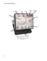
The bench (portable) model of the megohmmeter
is cased in a Flip-Tilt cabinet. The cabinet opens by
pushing down on the handle and tipping the instru-
ment into the desired operating position (paragraph
1.2).
2.6 Rack Mounting
Consult IET Labs.
2.7 Power Connections
Power connection to the rear panel is through
an ac inlet module comprised of an ac connector
and fuse drawer. Always use an outlet that has a
properly connected protection ground.
The 1863 and 1864 Megohmmeters can be operated
from either a 100- to 125-V or a 200- to 250-V, 50-to
400-Hz power line.
B e f o r e c o n n e c t i n g t h e 3 - w i r e I E C
power cord to the line, set the slide switch on the rear
panel to the proper setting as indicated by the position
of the white line on the slide switch. The slide can
be actuated with a screwdriver blade. Verify that the
correct size fuse for the input voltage selected has
been installed (1/4 A slow blow for 100-125 V input
or 1/8 A slow blow for 200-250 V input).
To change the fuse, proceed as follows: Proce-
dure
1. Make sure the unit has been discon-
nected from its ac power source for at least
fi
ve minutes before proceeding.
2. Remove the fuse drawer by inserting
a small
fl
at head screwdriver behind the small
tab to force the draw outward.
3. Once the fuse drawer has been com-
pletely removed from the instrument the fuse
maybe removed.
4. Remove the active fuse from the holder
and insert the replacement fuse into the fuse
holder.
5. Once the fuse has been installed in the
holder and spare fuse (if desired) installed in
the right side of the tray insert the tray back
into the fuse drawer, push in and lock.
Only use a three-conductor AC power cord to connect
the cabinet (if used) and the instrument to an electrical
ground (safety ground).
Plug the supplied IEC power cord into the instrument
into a power receptacle that has a ground. The power
cord may of course be selected to match the available
receptacle.
2.8 Environmental
Do not operate the instrument in the presence
of
fl
ammable gasses or fumes.
The 1863 and 1864 Megohmmeters are for
indoor use only.
There are no special requirements for ventila-
tion.
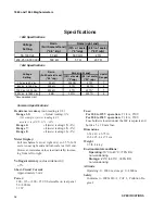
Temperature and Humidity
Operating:
10°C to 40°C; <70% RH
non-condensing
Storage:
-20°C to 60°C ; <80% RH
non-condensing
Altitude
Operating: 0 - 2000 m; storage: 0 - 4600 m
Summary of Contents for 1863
Page 18: ...1863 and 1864 Meghommeters 4 INTRODUCTION...
Page 34: ...APPLICATIONS 1863 and 1864 Meghommeters 20 This page intentionally left blank...
Page 44: ...SERVICE AND MAINTENANCE 1863 and 1864 Meghommeters 30 This page intentionally left blank...
Page 45: ...1863 and 1864 Meghommeters 31 PARTS LISTS AND DIAGRAMS Chapter 7 PARTS LISTS AND DIAGRAMS...
Page 46: ...32 PARTS LISTS AND DIAGRAMS...
Page 47: ...1863 and 1864 Meghommeters 33 PARTS LISTS AND DIAGRAMS...
Page 50: ...36 PARTS LISTS AND DIAGRAMS Figure 7 3 Type 1863 switching diagram...
Page 52: ...38 PARTS LISTS AND DIAGRAMS Figure 7 6 Type 1863 schematic diagram...
Page 53: ...1863 and 1864 Meghommeters 39 PARTS LISTS AND DIAGRAMS Figure 7 7 Type 1864 switching diagram...
Page 55: ...1863 and 1864 Meghommeters 41 PARTS LISTS AND DIAGRAMS Figure 7 9 Type 1864 schematic diagram...
Page 56: ...42 PARTS LISTS AND DIAGRAMS Figure 7 10 Complete cabinet assembly P N 4182 2328...
Page 57: ...1863 and 1864 Meghommeters 43 PARTS LISTS AND DIAGRAMS...
Page 58: ...44 PARTS LISTS AND DIAGRAMS...

