THEORY
1863 and 1864 Meghommeters
21
Chapter 5
THEORY
5.1 Theory Overview
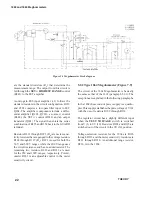
The 1863 and 1864 Megohmmeters consist of a
regulated dc power supply, a set of precision resistors,
and a FET-input voltmeter (Figure 5.1). Switch S
1
is
closed in the
DISCHARGE
position of the function
switch and open in the
CHARGE
and
MEASURE
positions. Switch S
2
is open
only
in the
MEASURE
position.
The regulated voltage, E, is controlled by a resistance
R
A
. A fraction, E
M
of the meter output voltage,
E
X
R
S
/R
X
is added to E to keep the voltage on the
unknown, E
X
, more constant and thus improve the
meter accuracy. A meter sensitivity resistor, R
B
, is
ganged to the voltage control resistor, R
A,
to make
the meter reading independent of applied voltage, (as-
suming that the unknown has no voltage coef
fi
cient).
An inverse scale is used on a reversed meter to give
a reading proportional to R
X
(and not its reciprocal)
and yet have a scale that increases from left to right
(0 to
∞
).
Metal-
fi
lm standard resistors are used on all ranges.
The top range of each instrument uses feedback to
effectively multiply the value of the previous standard
resistor by a factor of ten. In the 1863 the 200 M
Ω
resistor is multiplied to 2 G
Ω
; in the 1864 the 2 G
Ω
resistor is multiplied to 20 G
Ω
. The speci
fi
cations are
again broadened to allow for the tolerance variations
of this multiplication.
The voltmeter uses a FET-input, four-stage, unity-gain
ampli
fi
er (AMP, Figure 5.2) to obtain high stability
and low drift. The
SET
∞
control on both instruments
is a voltage balance control, while the
SET
∞
HIGH-
EST RANGE
control compensates for the FET gate
current on the highest ranges.
5.2 Circuit Description
The following paragraphs relate speci
fi
c components
from the schematic diagrams of the 1863 (Figure 7.6)
and 1864 (Figure 7.9) to the general components
shown in Figure 5.1.
5.2.1 Type 1863 Megohmmeter (Figure 7.6)
The voltage supply section (RECT.) of the 1863
consists of
fi
ve different circuits, three dc and two ac.
One ac circuit is a voltage source for the three pilot
lamps used, two to indicate the measurement range
(P101, P102) and the third to light the
DANGER
indicator (P103). The second supplies
fi
lament volt-
age to the vacuum tube V101.
The
fi
rst dc supply is a half-wave recti
fi
er circuit with
a 24-V Zener diode (CR 111) that supplies voltages
to the ampli
fi
er (AMP) circuit. A second dc supply
is a voltage doubler (CR101-CR104, C101-C102)
that supplies the plate voltage to V101. The voltage
to the plate is the same for the 50- to 250-V ranges
but R109 is eliminated from the circuit for the 500
V range. The third dc supply is a half-wave recti
fi
er
with a 20-V Zener diode (CR211) to supply voltage
levels to run the unity-gain ampli
fi
er (+1).
Tube V101 is a series regulator that is controlled by
the 5.6 V Zener diode (CR112, REF) and the setting
of R140.The voltage picked off R 140 is fed into
one side (Q102) of the differential ampli
fi
er (Q102,
Q103) while part of the output voltage is fed into the
other side (Q103). The output of the ampli
fi
er is fed
to the base of Q101 (AMP) and then to the grid of
V101 for controlling the output voltage.
The output selection resistors are R124 through
R127 (R
A
). These resistors along with the voltage
(E
M
) developed across R138, determine the TEST
VOLTAGE level. Resistors R211 through R219
Summary of Contents for 1863
Page 18: ...1863 and 1864 Meghommeters 4 INTRODUCTION...
Page 34: ...APPLICATIONS 1863 and 1864 Meghommeters 20 This page intentionally left blank...
Page 44: ...SERVICE AND MAINTENANCE 1863 and 1864 Meghommeters 30 This page intentionally left blank...
Page 45: ...1863 and 1864 Meghommeters 31 PARTS LISTS AND DIAGRAMS Chapter 7 PARTS LISTS AND DIAGRAMS...
Page 46: ...32 PARTS LISTS AND DIAGRAMS...
Page 47: ...1863 and 1864 Meghommeters 33 PARTS LISTS AND DIAGRAMS...
Page 50: ...36 PARTS LISTS AND DIAGRAMS Figure 7 3 Type 1863 switching diagram...
Page 52: ...38 PARTS LISTS AND DIAGRAMS Figure 7 6 Type 1863 schematic diagram...
Page 53: ...1863 and 1864 Meghommeters 39 PARTS LISTS AND DIAGRAMS Figure 7 7 Type 1864 switching diagram...
Page 55: ...1863 and 1864 Meghommeters 41 PARTS LISTS AND DIAGRAMS Figure 7 9 Type 1864 schematic diagram...
Page 56: ...42 PARTS LISTS AND DIAGRAMS Figure 7 10 Complete cabinet assembly P N 4182 2328...
Page 57: ...1863 and 1864 Meghommeters 43 PARTS LISTS AND DIAGRAMS...
Page 58: ...44 PARTS LISTS AND DIAGRAMS...

