SERVICE AND MAINTENANCE
1863 and 1864 Meghommeters
24
16.
Set the POWER/OFF
switch to
OFF
and
disconnect the decade resistor.
17. Connect the Digital Multimeter between the
GUARD
and
-UNKNOWN
terminals
with two single banana plug patch
cords.
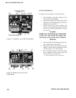
18. Connect the two ground terminals together
with a third patch cord (Figure 6.1).
The megohmmeter shorting link
should remain attached only to the
ground terminal.
18. Set the multiplier switch in the full ccw posi-
tion (1M, 100k) and the function switch
to MEASURE.
19. Measure the various standard resistors of the
megohmmeter with the DMM according
to the settings and tolerances of Table
6.2. Use the IET LOM-510A megohm-
meter for resistance values beyond the
range of the DMM.
Figure 6-1. Connections for measuring standard
resistors
Summary of Contents for 1863
Page 18: ...1863 and 1864 Meghommeters 4 INTRODUCTION...
Page 34: ...APPLICATIONS 1863 and 1864 Meghommeters 20 This page intentionally left blank...
Page 44: ...SERVICE AND MAINTENANCE 1863 and 1864 Meghommeters 30 This page intentionally left blank...
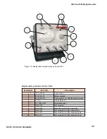
Page 45: ...1863 and 1864 Meghommeters 31 PARTS LISTS AND DIAGRAMS Chapter 7 PARTS LISTS AND DIAGRAMS...
Page 46: ...32 PARTS LISTS AND DIAGRAMS...
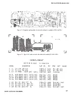
Page 47: ...1863 and 1864 Meghommeters 33 PARTS LISTS AND DIAGRAMS...
Page 50: ...36 PARTS LISTS AND DIAGRAMS Figure 7 3 Type 1863 switching diagram...
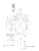
Page 52: ...38 PARTS LISTS AND DIAGRAMS Figure 7 6 Type 1863 schematic diagram...
Page 53: ...1863 and 1864 Meghommeters 39 PARTS LISTS AND DIAGRAMS Figure 7 7 Type 1864 switching diagram...
Page 55: ...1863 and 1864 Meghommeters 41 PARTS LISTS AND DIAGRAMS Figure 7 9 Type 1864 schematic diagram...
Page 56: ...42 PARTS LISTS AND DIAGRAMS Figure 7 10 Complete cabinet assembly P N 4182 2328...
Page 57: ...1863 and 1864 Meghommeters 43 PARTS LISTS AND DIAGRAMS...
Page 58: ...44 PARTS LISTS AND DIAGRAMS...


