1863 and 1864 Meghommeters
27
SERVICE AND MAINTENANCE
6.5.3 Range-Resistor Accuracy
The range resistors can be checked by performing
steps t through w of paragraph 6.2.
6.5.4 Coarse
∞
Adjustment
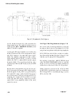
If it is impossible to set the in
fi
nity controls on the
front panel, set both controls at their center positions
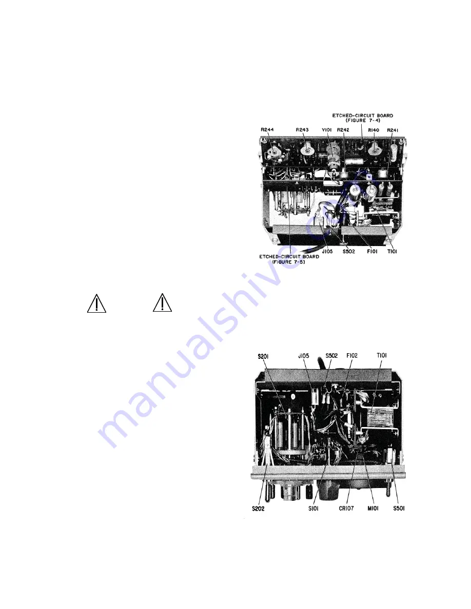
and adjust R244 (Figures 6-2 and 6-4), located on the
etched-circuit board with R140, for a reading as close
to
∞
as possible. Make the
fi
nal adjustments with the
front-panel controls.
6.6 Knob Removal
If it should be necessary to remove the knob on a
front-panel control, either to replace one that has
been damaged or to replace the associated control,
proceed as follows:
1. Grasp the knob fi rmly with the fi ngers, close
into the panel (or the indicator dial, if ap-
plicable), and pull the knob straight away
from the panel.
CAUTION
Do not pull on the dial to remove a
dial/knob assembly. Always remove
the knob fi rst. To avoid damage to the
knob and other parts of the control,
do not pry the knob loose with a
screwdriver or similar flat tool, and
do not attempt to twist the Knob from
the dial.
2. Observe the position of the setscrew in the
bushing, with respect to any panel markings
(or at the full ccw position of a continuous
control).
3. Release the setscrew and pull the bushing
off the shaft.
4. Remove and retain the black nylon thrust
washer.
NOTE
To separate the bushing from the knob, if for any
reason they should be combined off the instru-
ment, drive a machine tap a turn or two into the
bushing for a suf
fi
cient grip for easy separation.
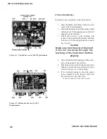
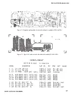
Figure 6-2. Top interior view of 1863 Megohmmeter
Figure 6-3. Bottom interior view of 1863
Megohmmeter
Summary of Contents for 1863
Page 18: ...1863 and 1864 Meghommeters 4 INTRODUCTION...
Page 34: ...APPLICATIONS 1863 and 1864 Meghommeters 20 This page intentionally left blank...
Page 44: ...SERVICE AND MAINTENANCE 1863 and 1864 Meghommeters 30 This page intentionally left blank...
Page 45: ...1863 and 1864 Meghommeters 31 PARTS LISTS AND DIAGRAMS Chapter 7 PARTS LISTS AND DIAGRAMS...
Page 46: ...32 PARTS LISTS AND DIAGRAMS...
Page 47: ...1863 and 1864 Meghommeters 33 PARTS LISTS AND DIAGRAMS...
Page 50: ...36 PARTS LISTS AND DIAGRAMS Figure 7 3 Type 1863 switching diagram...
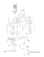
Page 52: ...38 PARTS LISTS AND DIAGRAMS Figure 7 6 Type 1863 schematic diagram...
Page 53: ...1863 and 1864 Meghommeters 39 PARTS LISTS AND DIAGRAMS Figure 7 7 Type 1864 switching diagram...
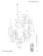
Page 55: ...1863 and 1864 Meghommeters 41 PARTS LISTS AND DIAGRAMS Figure 7 9 Type 1864 schematic diagram...
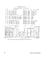
Page 56: ...42 PARTS LISTS AND DIAGRAMS Figure 7 10 Complete cabinet assembly P N 4182 2328...
Page 57: ...1863 and 1864 Meghommeters 43 PARTS LISTS AND DIAGRAMS...
Page 58: ...44 PARTS LISTS AND DIAGRAMS...


