background image

1

Introduction

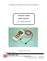
LOM-4000 Series

Chapter 1

INTRODUCTION

1.3 Case Design

The case is ruggedly constructed from ABS plastic.
The front panel is a reverse-printed polycarbonate
overlay with clear and unambiguous text. The batter-
ies are housed in a removable cassette for quick and
easy replacement.

1.4 Available Accessories

Supplied:

1

Set of test leads

1

Set of alkaline batteries

1          Operation Manual

Optional Lead Sets:

HSO1-P

Duplex Handspikes with 2.5-meter

                        leads, for Kelvin measurements of
                        plates or buss bars

HSO2-P

Similar to HSO1-P but with 2.5-

                        meter and 15-meter leads

LSO3-P

Large Kelvin clips with 3-meter leads
– accept cables and bars up to 38
mm in  diameter

LSO4-P

Similar to LSO3 but with 3-meter
and 15-meter leads

Other Optional Accessories:

CO1

1 Meter Cable-Test Fixture – Wood Base

CO2

1 Meter Cable-Test Fixture – Metal Base

MTS2

  Calibration Standard

For most efficient operation, a spare battery

cassette (

BP-02

) is recommended.

1.1 General Description

The LOM-4000 and LOM-4001 are accurate bench/
portable handheld Digital Milli-ohmmeters for the mea-
surement of resistance in the range 10 µ

Ω 

to 4000 

.

They utilize the four-terminal (Kelvin) resistance-mea-
surement method to eliminate the effects of lead re-
sistance.  The measured values are displayed on a 4-
digit, 4000-count LED display; there is also an over-
flow indicator. The LOM-4001 allows temperature
compensation of readings and temperature measure-
ment if the user connects a 100-ohm platinum-resis-
tance thermometer (PRT).

Simple push-button or auto-range selection of the
range required makes the LOM-4000 Series easy to
use.  Error and status warnings are illuminated when
appropriate.  The unit will withstand accidental appli-
cation of line voltage to the measuring terminals.

1.2 Theory of Operation

The measurement is true 4-terminal, using the Kelvin
principle.  A stable current is produced across the
resistance to be measured via the current (I) termi-
nals, and the voltage drop across the unknown resis-
tance Rx is measured at the voltage (U) terminals.
This potential drop is then compared against the volt-
age drop across internal standards.  The ratio of these
is then converted to the resistance value of Rx and
displayed in ohms on the digital display. Use of  spe-
cially selected components assures high accuracy and
long-term stability .

Summary of Contents for LOM-4000

Page 1: ...om IET LABS INC 534 Main Street Westbury NY 11590 Standards Decades Strobes Sound Level Meters Bridges LOM 4000 SERIES Digital Ohmmeter User and Service Manual PRECISION INSTRUMENTS FOR TEST AND MEASU...

Page 2: ......

Page 3: ...at no charge when returned to IET Changes in this product not approved by IET or application of voltages or currents greater than those allowed by the specifications shall void this warranty IET shal...

Page 4: ...ARE USED TAKE ALL MEASURES TO AVOID ACCIDENTAL CONTACT WITH ANY LIVE COMPONENTS USE MAXIMUM INSULATION AND MINIMIZE THE USE OF BARE CONDUCTORS WHEN USING THIS INSTRUMENT Use extreme caution when worki...

Page 5: ...nts 5 3 4 1 Ohmmeter Connections 5 3 4 2 Start up 6 3 4 3 Measurement 6 3 4 4 Current Mode 7 3 4 5 Over Range 7 3 4 6 Open Circuit Lead 8 3 4 7 Low Battery 8 3 4 8 Connections 8 3 5 Protection 8 3 6 T...

Page 6: ...re 3 2 Combined current and potential probes Kelvin clips 6 Figure 3 3 Connections for resistance measurements with various DUT configurations 7 Figure 3 4 Connection Diagram for Pt100 plug viewed fro...

Page 7: ...themea surement of resistance in the range 10 to 4000 They utilize the four terminal Kelvin resistance mea surement method to eliminate the effects of lead re sistance The measured values are displaye...

Page 8: ...pproximately 20 ms for normal measurement 40 ms for average AVE mode Polarity Selectable positive or negative current flow by manually reversing test leads plus an average mode which automatically dis...

Page 9: ...3 Operation LOM 4000 Series Chapter 3 OPERATION Low Battery LED Units Indication 4000 Function Keys Display Value LED 4001 only Calibration Display Mode LED s 4001 only...

Page 10: ...LOM 4000 Series 4 Operation 0 0...

Page 11: ...unit for shipping damage and report any problem immediately to the carrier retain ing packaging materials for inspection 3 2 Safety This unit has been designed and tested in accordance with IEC Standa...

Page 12: ...ic zero sequence and finally sets to the 4 k range The unit is now ready to make mea surements The unit will shut off automatically after several minutes of inactivity If the internal checks indicate...

Page 13: ...d for measurements that are not in ductive in order to eliminate errors caused by ther malemfin themeasurementcircuitortestleads In the AVE mode the LOM D4000 1 takes readings with the current flowing...

Page 14: ...e volt age Measurements cannot be made if this warning message is displayed This warning will also be dis played if the current lead resistance is high 3 4 7 Low Battery The LOBAT LED will light when...

Page 15: ...ill show CODE for a few seconds and the 0000 with a flashing cursor under the first zero Enter the calibration code 9252 using the UP and DOWN keys to select the digits and the ZERO and AVE keys with...

Page 16: ...ndard connected to the instrument using the shorting clip supplied with the standard or a heavy wire All four leads between the instrument and the standard should remain connected Remove the short aft...

Page 17: ...n RMA number before return ing the unit directly to IET CAUTION Replace only with the correct fuse type shown below The input circuits are protected by a 1 A fuse located in a holder on the printed ci...

Reviews: