background image

SPECIFICATIONS

PRS-300 Series

3

Chapter 2

SPECIFICATIONS

For convenience to the user, the pertinent 

speci

fi

 cations are given in an OPERATING 

GUIDE, shown typically in Figure 2.1, af

fi

 xed 

to the case of the instrument.

2.1 Specifi cations

User interface: 

Numeric keypad to enter resistance value with digital 
display. 

Accuracy:

  ±(70 ppm + 1 m

Ω

) 2 and 4 Terminal at 

23°C ±5°C Also see section 2.2

Minimum setting:

 0.1 

Ω

Resolution:

 1 

μΩ

 or 6 digits

Range:

 0.1 

Ω

- 20 M

Ω

Stability: See section 2.2

Thermal emf: 

< 15 

μ

V

Maximum Load:

 2 A, 200 V (peak), 0.5 W whichever 

applies 

fi

 rst

Resistors: 

Precision wire-wound and metal foil

TC of Resistors: 

< 1 ppm/°C for R4 and above

RTD Tables:


9 RTD tables can be entered into memory to allow 
user selection of temperature and the correct value 
of resistance will automatically be programmed.  
PT-100 and PT-1000 tables for both Fahrenheit and 
Celsius are pre-programmed into memory locations 
1 to 4.

Adjustment:


Automatic adjustment procedure utilizing a high pre-
cision DMM eliminates the requirement for manual 
trimming of resistors.

AC Frequency Response:

Residual Capacitance Terminals to GND: < 850 pF

Resistance

Typical ac/dc difference @ 1 kHz

0.1 

Ω

 -10 k

Ω

<100 ppm

10 - 100 k

Ω

<200 ppm

100 k

Ω

 - 1 M

Ω

<1% 

1 - 20 M

Ω

<20%

Terminals

Four low-emf, gold-plated, tellurium-cop per 5-way 
bind ing posts are used for 

HI

 and 

LO

 ter mi nal pairs 

for 

CUR RENT

 and 

SENSE

GND 

bind ing post is 

con nect ed to the case, to the chassis ground and to 
the earth ground.  

Switching time: 

15 ms Max for relay switch time 

between values, typically < 1 ms.  

  < 20 ms to interpret command and switch via 

ieee.488 interface

Power requirements:


90 - 264 Vac , 47 - 63 Hz.  30 Watts Max. 

Environmental conditions: 

 Operating:  

 10°C to 40°C; <80% RH 

 Storage:  

 -40°C to 70°C 

Note: exposure to humidity >60% for extended 
periods of time can cause the resistors to drift 
some of which is reversible.  See 2.2 for more 
information

Dimensions: 

Bench model: 43 cm W x 8.9 cm H x 33 cm D (17” x 
3.5” x 13”) 

in front of panel

: 3.8 cm (1.5”).

Weight:


Bench model: 5.5 kg (12 lb); weight speci

fi

 cations 

are nominal.

Remote Control:

USB: 

USB Type B connector standard on rear panel

Remote Control Options:
IEEE: 


GPIB standard 24 pin connector, conforms to IEEE-
488.2; SCPI 1994.0 command set; Hardware or 
software con

fi

 gurable addressing range of 1 to 30.  

Ethernet: 

IEEE 802.3 compliant, Speeds  10 BaseT 
(10 Mb/s) and 100 BaseT (100 Mb/s), IP Address 
Static or DHCP, Factory setting 192.168.0.254 static

Summary of Contents for PRS-300 Series

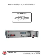
Page 1: ...TRUMENTS FOR TEST AND MEASUREMENT TEL 516 334 5959 800 899 8438 FAX 516 334 5988 www ietlabs com IET LABS INC PRS 300 SERIES Programmable Decade Resistance Substituters IEEE 488 2 Ethernet and USB Ope...

Page 2: ...TEL 516 334 5959 800 899 8438 FAX 516 334 5988 www ietlabs com IET LABS INC...

Page 3: ...ASUREMENT TEL 516 334 5959 800 899 8438 FAX 516 334 5988 www ietlabs com IET LABS INC Copyright 2017 IET Labs Inc PRS 300 IM June 2018 PRS 300 SERIES Programmable Decade Resistance Substituters IEEE 4...

Page 4: ...TEL 516 334 5959 800 899 8438 FAX 516 334 5988 www ietlabs com IET LABS INC PRECISION INSTRUMENTS FOR TEST AND MEASUREMENT...

Page 5: ...at no charge when returned to IET Changes in this product not approved by IET or application of voltages or currents greater than those allowed by the specifications shall void this warranty IET shall...

Page 6: ...E USED TAKE ALL MEASURES TO AVOID ACCIDENTAL CONTACT WITH ANY LIVE COMPONENTS USE MAXIMUM INSULATION AND MINIMIZE THE USE OF BARE CONDUCTORS WHEN USING THIS INSTRUMENT Use extreme caution when working...

Page 7: ...E APPLYING POWER Verify that all safety precautions are taken Make all connections to the instrument before applying power Note the instrument s external markings described under Safety Symbols GROUND...

Page 8: ...are hot and may cause personal injury if touched Disposal Waste Electrical and Electronic Equipment WEEE Directive 2002 96 EC This product complies with the WEEE Directive 2002 96 EC marking requireme...

Page 9: ...Instructions 6 3 4 Menu Structure 7 3 4 1 Main Menu 8 3 4 2 Setting a Resistance Value 8 3 4 3 Menu Button 8 3 4 4 Standard Values Screen 8 3 4 5 TABLE Key 9 3 4 6 Increment INCR Key 9 3 4 7 OPEN Key...

Page 10: ...l Considerations 23 8 1 3 Calibration Procedure 23 8 1 4 Adjustment of Internal Resistors 23 Chapter 9 PRS DMM Self Adjusting Software 25 9 1 PRS DMM Self Adjusting Softtware 25 9 1 1 PRS DMM Self Adj...

Page 11: ...ontacts from becom ing tarnished when unused or when only low currents are passed through them This is most often the case when only minute test currents are drawn by digital multimeters and other tes...

Page 12: ...ement for calibration applica tions and 2 wire mode for use in series as a substitute resistor and for RTD applications The front panel display indicates the mode selected 2 wire or 4 wire There are t...

Page 13: ...s to GND 850 pF Resistance Typical ac dc difference 1 kHz 0 1 10 k 100 ppm 10 100 k 200 ppm 100 k 1 M 1 1 20 M 20 Terminals Four low emf gold plated tellurium copper 5 way binding posts are used for H...

Page 14: ...cal electronic product in domestic household waste Product Category With reference to the equipment types in the WEEE Directive Annex I this product is classed as a Monitoring and Control instrumentat...

Page 15: ...chever applies first Resistors Precision wire wound and metal foil RTD Tables 9 RTD tables can be entered into memory to allow user selection of temperature and the correct value of resistance will au...

Page 16: ...SPECIFICATIONS PRS 300 Series 6...

Page 17: ...moved on the binding posts of the PRS 300 and the PRS 300 set to 4 Wire 2 Wire connection the gold shorting links must be used on the binding posts of the PRS 300 and the PRS 300 set to 2 Wire See sec...

Page 18: ...owing submenu 1 STANDARD VALUES 1 1 STD VALUES 2 5 STD VALUES 3 10 STD VALUES 4 RATIOMETRIC 2 CONFIGURE 1 LCD CONTRAST 2 2W 4W MODE 3 CALIBRATE 4 VERSION Press MENU to select one of the following 1 ST...

Page 19: ...3 4 4 Standard Values Screen There are 4 selections available in the STANDARD VALUES menu The operation of the standard values allows the PRS 300 to be used as an automated resistance carousel with bu...

Page 20: ...hen the screen will look like Figure 3 5 showing temperature on top line and resistance on the bottom line Figure 3 5 PR 100 C set to 0 25 C For negative temperatures press the 000 key prior to enteri...

Page 21: ...ng the MENU button selecting CONFIGURE pressing the 2 will change between 2 wire and 4 wire modes The use of 4W mode with Kelvin leads minimize the effects of contact resistance and gives best perform...

Page 22: ...built calibrated and intended for use in a laboratory environment with a nominal ambient temperature near 23o C The accuracy of the unit may be affected when operated in non laboratory environments Al...

Page 23: ...ally when the PRS 300 is connected to a computer using the USB port Windows 7 and higher will search for the correct driver and as long as the computer is connected to the internet the driver should a...

Page 24: ...PRS 300 Series IEEE INTERFACE OPTION 14...

Page 25: ...out is two min utes and it is recommended that the client issue a Space BS sequence on an occasional basis less than the timeout to reset the timeout counter VXI 11 Background VXI 11 is a communicatio...

Page 26: ...ng systems The Java jGpibEnet project on SourceForge was developed using an ICS 8065 Controller similar to the PRS Controller 5 4 Network Configuration This paragraph configures the 9006 card in the P...

Page 27: ...For Windows PCs right click on My Network Places and click on Properties Right click on Local Area Connection and click Properties Highlight Internet Protocol TCP IP and click Properties If your PC s...

Page 28: ...I 11 Configuration Utility Method The VXI 11 Configuration Utility program is called VXI11_config exe and runs in any WIN32 PC with Windows 98 Me 2K XP Vista 7 and Server 2003 operating systems The VX...

Page 29: ...e Find Server Help and Exit buttons are enabled on the program window The other buttons will be enabled as you advance through the program 5 Click on the Find Server button The program scans for all V...

Page 30: ...192 168 1 xxx range in step 3 your PC s network settings will have to be changed to communicate with the board Exit the VXI11_ config program and restore the PC s network settings 5 7 Resetting Defaul...

Page 31: ...tion and a command reference are located in Appendix A Other tutorials are available on line con sult IET for additional information A software GPIB keyboard can be found at www ietlabs com 6 2 Capabi...

Page 32: ...ERFACE OPTION 22 Unzip the file and follow instructions to install Open the application You may use the Find Listeners button to confirm that the PRS unit is recognized Other instruments may also be r...

Page 33: ...via any of the commands listed in Appendix B For USB and RS 232 interfaces lf cr or crlf can be used as terminator The device returns in this case crlf The device performs all commands previously sent...

Page 34: ...PROGRAMMING PRS 300 Series 24...

Page 35: ...y There should be no temperature gradients across the unit under test In the case of the PRS 300 a Kelvin type 4 wire test terminals should be used to obtain accurate low resistance readings Steps sho...

Page 36: ...ry The internal lead resistance does not need to be measured again unless repair has been per formed to the PRS 300 Below is a list of the 43 resistors and their nominal resistance value These resisto...

Page 37: ...lues To enter into the calibration process press the MENU key and then select 3 for calibration At the end of the process all cali bration values will be saved into memory At anytime pressing the MENU...

Page 38: ...300 Programmable Resistance Substituter Kelvin cables between PRS 300 and Fluke 8508A GPIB cables as necessary 9 1 3 Software Installation Install the PRS DMM Self Adjusting Software using the supplie...

Page 39: ...res and adjusts the PRS 300 to achieve the closest value possible to the entered target value The accuracy depends upon the MEASUREMENT SPEED See section 9 3 5 9 3 PRS DMM Settings 9 3 1 PRS DMM Setti...

Page 40: ...nd autorange ON The 8508A will also be configured for Low Current Fast AD Integration OFF and Analog Filter OFF If additional commands need to be sent to the DMM click on the Configure Button and ente...

Page 41: ...ents are made with 6 digits of resolution and measurements and adjustments are made until the accuracy is better than 40 ppm Fast measurements are made with 6 digits of resolution There are no adjustm...

Page 42: ...PRS 300 Series PRS DMM SOFTWARE 32...

Page 43: ...Semicolons separate messages Colons separate command words Commas separate data fields nl Line feed and or EOI as last character terminates a program message Line feed ASCII 10 and EOI terminates a RE...

Page 44: ...with line feed lf Response from the device also returns line feed lf IEEE 488 2 Common Commands IDN Returns instrument identification IET Labs PRS 300 Serial Number software version ESR Returns the r...

Page 45: ...treated as a single Message Unit with results sepa rated by commas If a particular test has None selected as a secondary parameter no place will be reserved for the null result As an example a sequenc...

Page 46: ...ion Complete This register is read by executing an ESR command page 76 except no Note that this is a destructive read Reading the register clears it Each bit of the Event register must be enabled in o...

Page 47: ...r Recalls resistance value from memory location 0 to 9 Number is 0 to 9 SYSTEM Commands SYSTem SERIal Ax xxxxxxxx Sets the serial number in non volatile memory serial num ber Serial number in the form...

Page 48: ...ed value of resistance in ohms into mem ory number is a floating point number representing the resistance value in ohms for the internal resistor being measured Each time the command CALI RES SET is u...

Page 49: ...0 is no table with display shown in ohms and 1 2 and 3 are user defined tables CONFigure TABLe SELect Returns table number that is selected CONFigure TABLe NAME name Sets Table name name is ASCII up...

Page 50: ...PRS 300 Series APPENDIX B 40...

Reviews: