OPERATION
PRS-300 Series
8
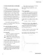
Default values are:
A
: 10 k
Ω
│
B
: 100
k
Ω
c) Press
RCL
then a number key (
0 – 9
)
to display a user-de
fi
ned value or a fac-
tory default value.
Default values are:
0
- 100
Ω
│
1
- 1
k
Ω
│
2
- 2 k
Ω
3.
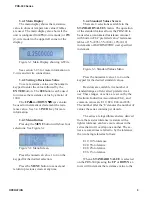
To prevent possible damage to
the PRS-300, set the maximum
applied voltage by pressing
VOLT
,
entering the voltage on the keypad, then
pressing
ENTER
. (Default: 0.5 V)
The
fi
rmware sets the minimum selectable
resistance value so that the power does not
exceed 1 W. To ensure that the whole range
of resistances is selectable,
VOLT
setting
must be
≤
1 V.
Rmin is limited to >V
2
, where V is the
VOLT setting.
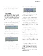
4. Select 2-wire or 4-wire mode by press-
ing the
MENU
button, selecting
CON-
FIGURE
, pressing the “2” will change
between 2-wire and 4-wire modes
In 2-wire mode shorting links must be in-
stalled across high and low terminal pairs.
In 4-wire remove the shorting links.
5. Connect to the circuit or device under test.
To isolate the PRS-300 from the application,
press
OPEN
to open the circuit. To close the
circuit, press
OPEN
again.
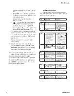
3.4 Menu Structure
The main table below show menu struc-
ture of the PRS-300 and basic function of each
button and menu selection.
Key
Description
Function
Basic operation
enter
enter button
Sets resistance value
0-9, 000/(-)
Used to enter numerical values. To select desired numerical
value, press value as required.
(-)
is used with tables for nega-
tive temperature
◄
Deletes the last character from
the display.
To delete the last character,
press
◄
.
Options
MENU
Displays the following submenu:
1. STANDARD VALUES
1: 1% STD VALUES
2: 5% STD VALUES
3: 10% STD VALUES
4: RATIOMETRIC
2. CONFIGURE
1: LCD CONTRAST
2: 2W / 4W MODE
3. CALIBRATE
4. VERSION
Press
MENU
to select one of the
following:
1. STANDARD VALUES - se-
lects increments for UP
and DOWN
keys
2. CONFIGURE - allows user
to adjust display contrast
and change between 2-wire
and 4-wire modes
3. CALIBRATE - see Section 8
4. VERSION - Displays cur-
rent
fi
rmware version and
release date.
INCR
Selects the increments for the
UP
and DOWN
keys
Default value: Ratiometric (0.8%
of displayed value)
To adjust increments:
1. Press
INCR
.
2. Enter desired increment
value on the keypad.
3. Press
ENTER
to save.
Storing and recalling resistance values
STO
Stores a resistance value in
memory locations A-D and 0-9.
To store a value, press
STO
and
then press the desired location
button A-D or 0-9.
A, B
Recalls a stored resistance
value.
Default values:
A
: 10 k
Ω
B
: 100 k
Ω
To change stored values:
1. Enter a resistance value
2. Press
STO
and then
A
,
B
RCL
Recalls a stored resistance
value from memory location 0-9.
To recall a stored value, press
RCL
, then press the desired
location button (0-9)
Limiting Current
VOLT
Sets voltage to limit the current
in order to protect the PRS-300
from possible damage.
Default value: 0.5 V
To adjust voltage:
1. Press
VOLT
.
2. Enter desired voltage on the
keypad.
3. Press
ENTER
to save.
Electrical Isolation
OPEN
Isolates the connection terminals
by establishing an open circuit.
To open the circuit, press
OPEN
.
To close, press
OPEN
again.
Option: Simulating RTD’s and transducers
TABLE
Loads up to 9 stored data
tables for simulating RTD’s or
transducers.
To select the desired table,
press
TABLE
to cycle through
the three options.
Summary of Contents for PRS-300 Series
Page 2: ...TEL 516 334 5959 800 899 8438 FAX 516 334 5988 www ietlabs com IET LABS INC...
Page 16: ...SPECIFICATIONS PRS 300 Series 6...
Page 24: ...PRS 300 Series IEEE INTERFACE OPTION 14...
Page 34: ...PROGRAMMING PRS 300 Series 24...
Page 42: ...PRS 300 Series PRS DMM SOFTWARE 32...
Page 50: ...PRS 300 Series APPENDIX B 40...


