IFAM SEGURIDAD, S.L.U.
Notario Etxagibel, 4. 20500 Arrasate-Mondragón (Spain)
MCA 200
MANUAL DE INSTRUCTIONES
INSTRUCTION MANUAL
NOTICE D’INSTALLATION
MANUAL de INSTRUçõeS
E
NGLI
SH
1
Before installation
1) Make sure that all parts work properly.
2) Choose and set a code following the instructions on “Setting / Changing
the entry code”. All of some of the buttons can be chosen to set the code.
There is no need to replicate the order of the buttons when entering the code
to open the door.
3) After setting the code, press the C button. Then try entering the code. The
door handle should easily turn. The bolt should go in and out freely as well.
4) Once you enter the code and turn the handle, it is compulsory to re-lock
the bolt by turning the knob to its original position. You can do this both from
the outside or the inside of the door.
2
Setting / changing the entry code
At the back of the Mechanical Code Lock
with Lever Handle (Fig . 1) you will find
the screw buttons corresponding
to the push buttons of the lock’s
front side. To set the code, turn the
selected screw buttons towards the G l
etter (Fig . 1B) with a screwdriver.
This operation activates the push buttons
on the front side.
To deactivate the push buttons, turn the
screw buttons towards the F letter (Fig . 1B).
Check that the code works properly before
installing the lock on the door.
ALWAYS PRESS KEY ‘C’ BEFORE ENTERING THE CODE
3
Installation
Determine door handing
This diagram helps you determine, depending on the position of the hinges, if
the door is on the left or right handed and if it opens inwards or outwards.
To open inwards, use the surface-mounted strike.
To open outwards, us the flush-mounted strike.
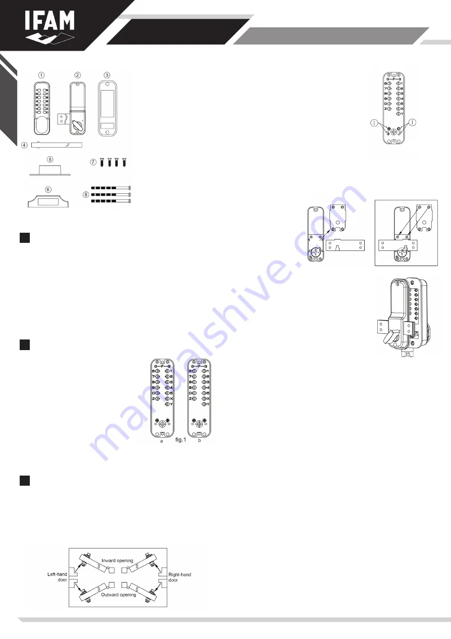
1) Mechanical Code Lock
with Lever Handle
2) Internal Block-Bolt
3) Neoprene Seals (2 pieces)
4) Spindle
5) Flush-mounted strike
6) Surface-mounted strike.
7) Wood screws (4 pieces) for
fixing keeper
8) Fixing bolt (3 in total, 1 spare)
Change to opposite handed door...
The MCA200 lock is valid for both left hand doors
and right hand doors.
If the door hading does not match
with the default configuration of your lock,
you can change the orientation of your MCA200 unit.
Remove the labels with the number 1 (see figure 2),
then remove the screw in one of the holes and
screw it into the opposite hole.
... Or alternatively by altering the direction on the bolt
a) Remove the 4 screws and the plate at the back of the internal block.
b) Remove the bolt and reverse it (on the left side or on the right side, the drive
sheave down).
c) Place the 4 washers on
the ‘nut’ parts.
d) Screw the plate back
to its position.
Positioning the lock
IMPORTANT: Determine which strike (flush-mounted
or surface-mounted) to be used and mark its position
on the frame before drilling the door.
CAUTION: The distance between the bolt and midlle of
the strike hole should be 35mm.
Present the internal block with the handle in vertical
position and hold it on the door with and end of the
bolt alligned with the frame where the strike will be
installed (see Step E)
Mark the position of the upper mounting hole using
the template at the back of the instruction manual and
mark the position of the lower mounting hole and the hole for the spindle.
Drill 7 mm holes for the attachment screws and one 9.5 mm hole for the spindle.
Fixing the lock
IMPORTANT Do not close the door before BEING SURE the code works properly.
The spindle is designed for a 35 to 65mm thick door.
For door thickness below 50mm, separate a size of 12 mm at the end of the
spindle.
Cut the end of attachment screws according to the thickness of the door so that
with the flanges with the screws hold the lock with three threads.
CAUTION: The lower attachment screw should be longer than the upper screw.
Hold the lock into position, the rear face and the neoprene flanges on the door
with the square into position. Screw all the elements starting by the upper
screws.
Fixing the strike plate
The strike plate must be positioned in a way that only the flat section of the
latch bolt can enter the deadbolt.
Once the correct position determined, drwa a contour and use this mark to
make a 1mm rebate to fit flush mounting. The strike must be aligned with the
frame. Otherwise, readjust with the drilling machine and/or a chisel, in order to
install the bolt.
Make sure that the deadbold stops on the strike to maitain its anti-burglar
function while the door is locked.
If necessary, drill or cut a recess for the latch bolt.
Fix the srtike plate with one screw. Then, test the lock to see if it works properly
and proceed to possible adjustments if necessary. Now, you can fix the strike
completely.
Fig. 2


